
1.1a. Front subframe, anti-roll bar, and anti-roll bar mounting parts:
1 - Cover, only on models with 2nd generation V6 engines;
2 - Bolt, 60 Nm, only on models with 2nd generation V6 engines;
3 - Vibration damper, only on models with 2nd generation V6 engines;
4 - Front final drive;
5 - Subframe;
6 - Self-locking nut, subject to replacement;
7, 8 - Bolt, subject to replacement, 90 Nm, then tighten to an angle of 90°;
9 - Glued rubber bushing;
10 - Thrust washer, 4.2 TDI models only, slot facing rear of vehicle;
11 - Bolt, to be replaced, 120 Nm, then tighten to an angle of 90°;
12 - Self-locking nut, replaceable, 180 Nm;
13 - Eccentric washer;
14 - Eccentric bolt;
15 - Lower control arm, beveled pin should not be lubricated;
16 - Bolt, to be replaced, 120 Nm, then tighten to an angle of 180°;
17, 21 - Self-locking nut, subject to replacement, 110 Nm;
18 - Stabilizer link 23;
19, 22 - Bolt;
20 - Suspension strut;
23 - Stabilizer bar;
24 - Stabilizer bushing 23;
25 - Clamp;
26 - Bolt, 60 Nm.
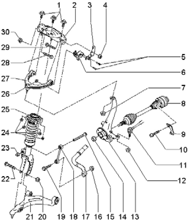
1.1b. Suspension strut mounting parts (with a spring), upper arm, its bracket and suspension height sensor:
1 - Bolt, to be replaced, 50 Nm, then tighten to an angle of 90°;
2 - Bracket of rack 25 and lever 27;
3 - Sensor bracket 6;
4, 30 - Self-locking nut, subject to replacement, 50 Nm, then tighten to an angle of 90°;
5 - Bolt, 5 Nm;
6 - Front suspension height sensor (left or right);
7 - Self-locking nut, replaceable, 85 Nm;
8 - Drive shaft;
9 - Locking plate;
10 - Bolt, must be replaced; 50 Nm (M10) or 90 Nm (M12), then tighten to an angle of 90°;
11 - Tie rod end;
12 - Self-locking nut, replaceable, 90 Nm;
13 - Steering knuckle; conical holes should not be lubricated;
14 - Self-locking hub nut, subject to replacement, 500 Nm;
15, 19 - Bolt;
16, 23 - Self-locking nut, subject to replacement, 110 Nm;
17 - Stabilizer bar;
18 - Stabilizer link 17;
20 - Self-locking nut, replaceable, 150 Nm, then tighten to an angle of 90°;
21 - Lower suspension arm;
22, 28, 29 - Bolt, subject to replacement;
24 - Self-locking nut, replaceable, 30 Nm;
25 - Suspension strut;
26 - Self-locking nut, 7 Nm;
27 - Upper suspension arm.
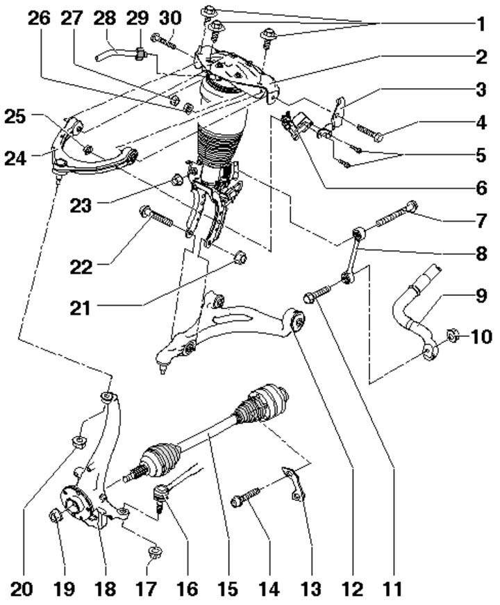
1.1c. Suspension strut mounting parts (pneumatic), upper arm and suspension height sensor:
1, 4 - Bolt, subject to replacement, 50 Nm, then tighten to an angle of 90°;
2 - Air shock absorber;
3 - Sensor bracket 6;
5 - Bolt, 5 Nm;
6 - Front suspension height sensor (left or right);
7, 11 - Bolt;
8 - Stabilizer link 9;
9 - Anti-roll bar;
10, 23 - Self-locking nut, subject to replacement, 110 Nm;
12 - Lower suspension arm;
13 - Locking plate;
14 - Bolt, must be replaced; 50 Nm (M10) or 90 Nm (M12), then tighten to an angle of 90°;
15 - Drive shaft;
16 - Tie rod end;
17 - Self-locking nut, replaceable, 90 Nm;
18 - Steering knuckle; conical holes should not be lubricated;
19 - Self-locking hub nut, subject to replacement, 500 Nm;
20 - Self-locking nut, replaceable, 85 Nm;
21 - Self-locking nut, must be replaced, 150 Nm, then tighten to an angle of 90°;
22 - Bolt, must be replaced;
24 - Upper suspension arm;
25 - Self-locking nut, 7 Nm;
26, 27 - Self-locking nut, subject to replacement;
28 - Pneumatic tube; left - purple, right - green;
29 - Air bleed connection, 5 Nm;
30 - Bolt, to be replaced, 50 Nm, then tighten to an angle of 90°.
The installation details of the steering knuckle and the front wheel hub assembly are shown on illustrations 8.1 Chapter 7.
Rear suspension - independent, multi-link, steering, with trapezoidal lower wishbone, anti-roll bar and MacPherson struts, or air struts (with adjustable height and damping). The installation details of the suspension components are shown in illustrations 1.2ad.
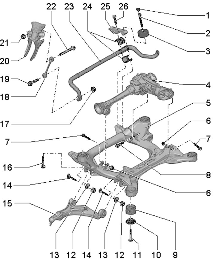
1.2a. Subframe and stabilizer bar of the rear suspension:
A - Forward direction;
1 - Rear final drive;
2 - Lock washer, must be replaced;
3 - Glued front rubber hydraulic bushing;
4, 22, 23 - Protection from stones;
5, 20 - Spacer sleeve;
6 - Subframe;
7 - Bolt, must be replaced;
8 - Self-locking nut, replaceable, 90 Nm, then tighten to an angle of 90°;
9 - Bolt, to be replaced, 90 Nm, then tighten to an angle of 90°;
10 - Glued rear rubber hydraulic bushing;
11, 24 - Bolt, 1 Nm;
12 - Right stabilizer bar 13;
13 - Stabilizer bar;
14, 19 - Stabilizer bushing 13;
15 - Bolt, 50 Nm;
16 - Clamp;
17 - Left stabilizer bar 13;
18 - Self-locking nut, replaceable, 100 Nm;
21 - Bolt, to be replaced, 120 Nm, then tighten to an angle of 180°.
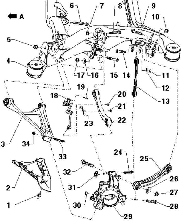
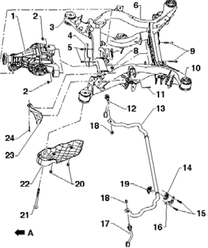
1.2b. Rear suspension arms and height sensor:
A - Forward direction;
1 - Spacer sleeve;
2 - Protection from stones;
3 - Lower suspension arm;
4 - Subframe;
5, 27, 30, 34 - Self-locking nut, subject to replacement;
6, 28, 32, 33 - Bolt, subject to replacement, 150 Nm, then tighten to an angle of 90°;
7, 10 - Self-locking nut, subject to replacement, 90 Nm, then tighten to an angle of 90°;
8, 9 - Bolt, subject to replacement;
11, 17 - Self-locking nut, subject to replacement, 180 Nm;
12, 16 - Eccentric washer;
13 - Guide lever;
14, 15 - Eccentric bolt;
18 - Rear suspension height sensor (left or right);
19 - Bolt, 4 Nm;
20, 21 - Self-locking nut, subject to replacement, 8 Nm;
22 - Upper front control arm;
23 - Bracket;
24 - Bolt, to be replaced, 150 Nm, then tighten to an angle of 90°;
25 - Upper rear arm;
26 - Washer;
29 - Hub assembly holder;
31 - Self-locking nut with lock plate, subject to replacement.
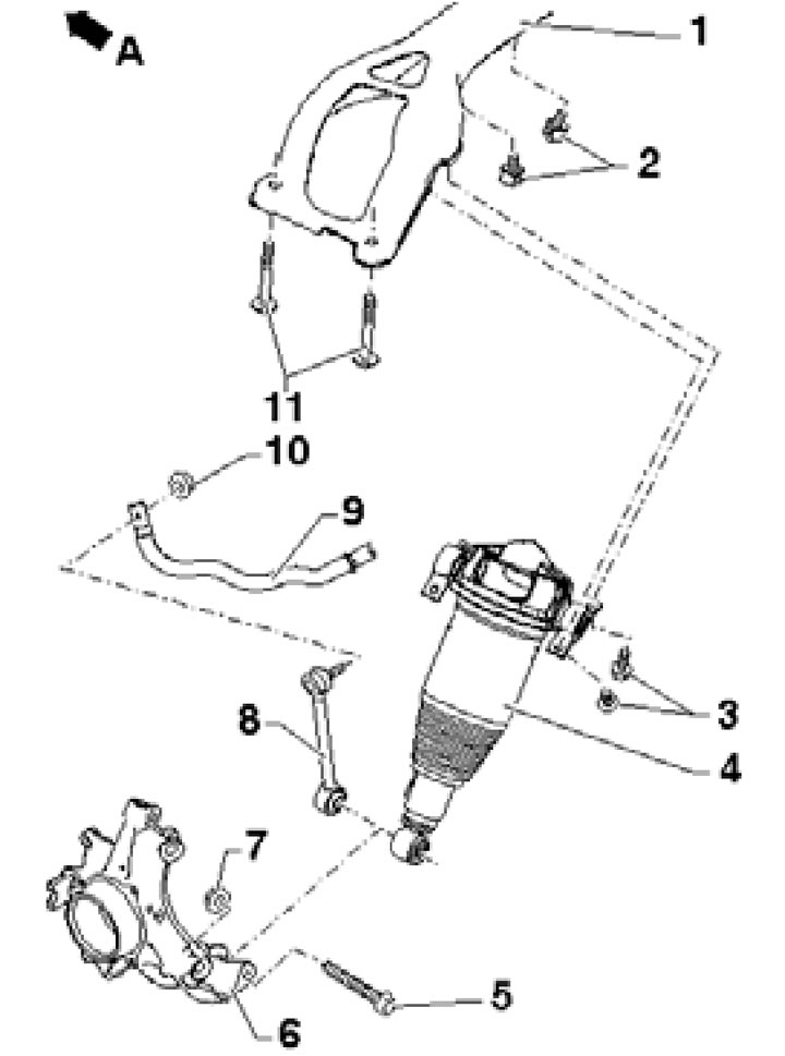
1.2s. Air shock absorber and cross member:
A - Forward direction;
1 - Crossbar;
2 - Retainer;
3 - Bolt, 60 Nm;
- Air shock absorber;
5 - Bolt, to be replaced, 90 Nm, then tighten to an angle of 90°;
6 - Hub assembly holder;
7 - Self-locking nut, subject to replacement;
8 - Stabilizer link 9;
9 - Anti-roll bar;
10 - Self-locking nut, replaceable, 100 Nm;
11 - Bolt, to be replaced, 90 Nm, then tighten to an angle of 120°.
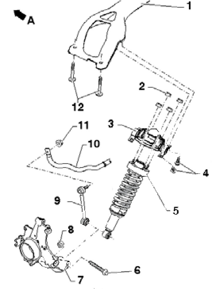
1.2d. Suspension strut (with a spring) and crossbar:
A - Forward direction;
1 - Crossbar;
2 - Self-locking nut, replaceable, 30 Nm;
3 - Rack bracket 5;
4 - Bolt, 60 Nm;
5 - Suspension strut, can be removed only with bracket 3;
6 - Bolt, to be replaced, 90 Nm, then tighten to an angle of 90°;
7 - Hub assembly holder;
8 - Self-locking nut, subject to replacement;
9 - Stabilizer link 10;
10 - Stabilizer bar;
11 - Self-locking nut, replaceable, 100 Nm;
12 - Bolt, to be replaced, 90 Nm, then tighten to an angle of 120°.
The installation details of the rear suspension strut and hub assembly are shown in Illustration 10.1 of Chapter 7.
The chassis modification can be identified by the PR number on the vehicle data sticker located on the floor of the luggage compartment and in the service book (see Introduction), PR numbers, indicating the modification of the chassis, as well as the front and rear suspensions, are located in the bottom line (see illustration 1.3).
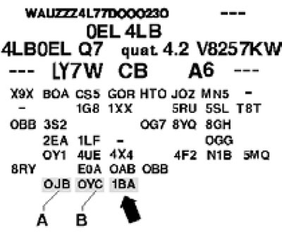
1.3. Chassis PR numbers:
A - Front suspension;
B - Rear suspension;
Arrow - Chassis.
Suspension PR numbers can be used to select shock absorber combinations.
Steering system - consists of a steering wheel, steering shaft, maintenance-free rack-and-pinion steering mechanism and steering drive. The steering wheel with a built-in front driver airbag is mounted on a shaft that transmits steering movements to the steering gear. The steering column switch assembly is installed behind the steering wheel. To maintain contact between the airbag and the SRS control unit when the steering wheel is turned, a coil spring is used that can twist and untwist. The coil spring consists of a tape with internal conductive tracks. The steering column can be adjusted for both reach and tilt.
To make driving easier, the vehicle is equipped with a hydraulic power steering system with a gain factor that depends on the vehicle speed.
When performing repairs or maintenance on suspension and steering components, problems often arise with loosening "stuck" bolts and nuts. The fastening elements located under the bottom of the car are constantly exposed to external influences and, over time, become corroded and partially destroyed. Using brute force to loosen such a "stuck" fastener carries the risk of damaging it. First, wet the stubborn part with a small amount of a special penetrating liquid (for example, WD-40), allowing it to thoroughly soak into the rust layer. Use a wire brush to remove external deposits from accessible areas of the threaded surfaces. Sometimes a sharp blow with a hammer on the nut through a drift helps to break up the rust filling the gaps between the threads of the threaded joint - try not to damage the threads as a result of the drift slipping off. Using a long ratchet to loosen a stuck fastener can significantly increase the torque applied. However, remember that using extensions with ratchet drives carries the risk of damage to the return mechanism and the risk of injury. Self-locking nuts and fasteners damaged by corrosion or removal during repairs must be replaced without fail. Welding and straightening are not permitted on load-bearing bearings and on suspension components that guide the wheel.
Since most of the procedures described in this chapter are performed with the vehicle raised off the ground, you should take care in advance of ways to securely fix it in the raised position. - prepare strong supports. Jacking instructions are described in the Introduction. To jack up your vehicle, use a hydraulic jack. Remember that the standard onboard jack is only intended for temporary jacking when replacing a flat tire. A hydraulic jack can also be used to lift some suspension components while performing a particular procedure. Before carrying out any work, secure the vehicle to the lift legs using safety belts.
Attention: It is not permitted to carry out work under a vehicle that is held in a raised position only by means of jacks!
If after lowering the vehicle it continues to rest on the lift legs even after the jacking mode is turned off (insufficient pressure in the shock absorbers), start the engine to turn on the compressor and build up pressure in the shock absorbers. In addition, the compressor can be started using diagnostic equipment.
The original article is available on the online resource: audimanual.ru