



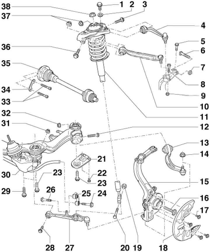
1.1. Front suspension parts 1. Bolt, 75 Nm; 2. Washer; 3. Bolt, subject to replacement; 4. Rear upper link; 5. Wheel alignment bolt, 5 Nm, must be replaced; 6. Bolt; 7. Self-locking nut, 45 Nm, subject to replacement; 8. Bolt, 40 Nm; 9. Self-locking nut, subject to replacement; 10. Front Upper Link; 11. Suspension shock absorber strut; 12. Bolt, subject to replacement, 70 Nm, then tighten to an angle of 180°; 13. Lower guide rod; 14. Nut, 110 Nm, subject to replacement; 15. Wheel bearing housing; 16. Flange bolt, subject to replacement; 17. Flange bolt, 10 Nm; 18. Brake mechanism shield; 19. Self-locking nut, subject to replacement; 20. Bolt, 90 Nm; 21. Subframe support; 22. Bolt, 55 Nm; 23. Bolt, to be replaced, 110 Nm, then tighten to an angle of 90°; 24. Bolt, subject to replacement, 40 Nm, then tighten to an angle of 90°; 25. Crossbar stabilizer bar; 26. Bolt, to be replaced, 40 Nm, then tighten to an angle of 90°; 27. Lower support arm; 28. Bolt, subject to replacement, 70 Nm, then tighten to an angle of 180°; 29. Bolt, 75 Nm, subject to replacement; 30. Subframe; 31, 32. Self-locking nut, subject to replacement; 33. Bolts M8/M10, pre-tighten all bolts with a force of 15 Nm, and then finally with a force of 40 // 70 Nm; 34. Locking plate; 35. Drive shaft; 36. Bolt, subject to replacement; 37. Self-locking nut, to be replaced, 50 Nm, then tighten to an angle of 90°; 38. Flange nut, subject to replacement, 50 Nm
Rear suspension - independent, with trapezoidal traction. Springs and shock absorbers are installed separately. Rear suspension installation details are shown in illustrations 1.2ad.
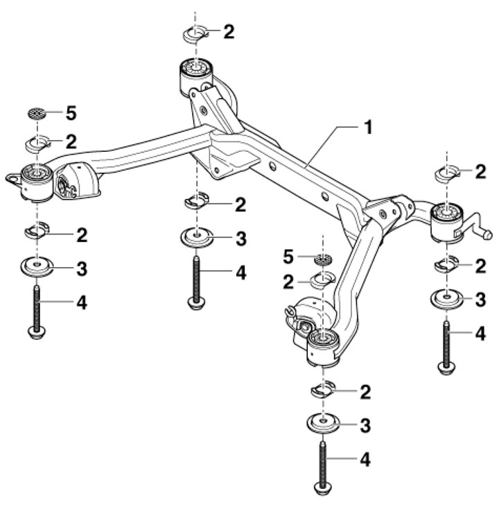
1.2a. Rear suspension subframe parts for FWD models 1. Subframe; 2. Plastic insert; 3. Washer, subject to replacement; 4. Bolt with washer, subject to replacement, 110 Nm, then tighten to an angle of 90°; 5. Washer, installed only at the front, with the recess towards the body
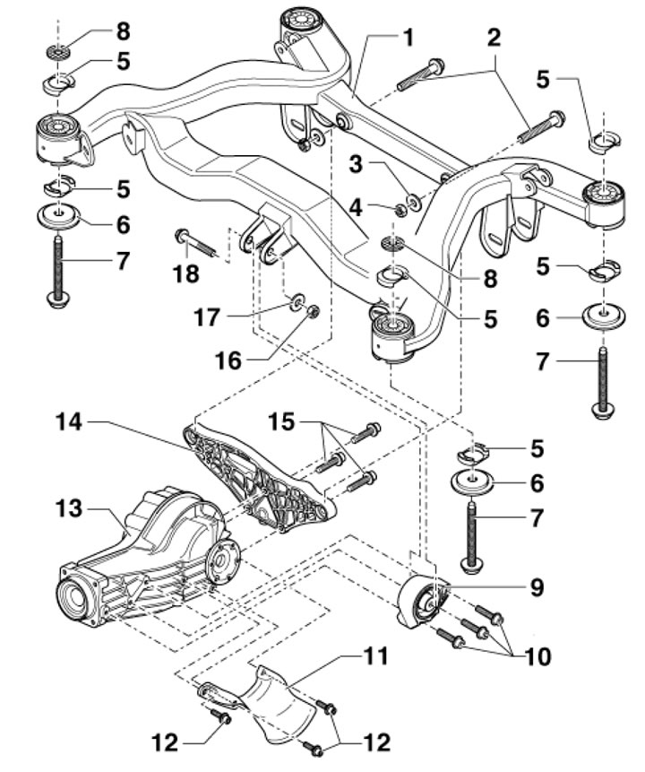
1.2b. Rear Suspension Subframe Parts for AWD Models 1. Subframe; 2. Bolt with washer, 55 Nm; 3. Washer; 4. Nut; 5. Plastic insert (part of the bushing); 6. Washer, subject to replacement; 7. Bolt with washer, subject to replacement, 110 Nm, then tighten to an angle of 90°; 8. Washer, installed only at the front, with the recess towards the body; 9. Front support of the rear differential; 10, 15. Bolt with washer, 40 Nm; 11. Heat shield; 12. Bolt with washer, 25 Nm; 13. Rear differential; 14. Rear crossmember; 16. Nut, 40 Nm; 17. Washer; 18. Bolt with washer
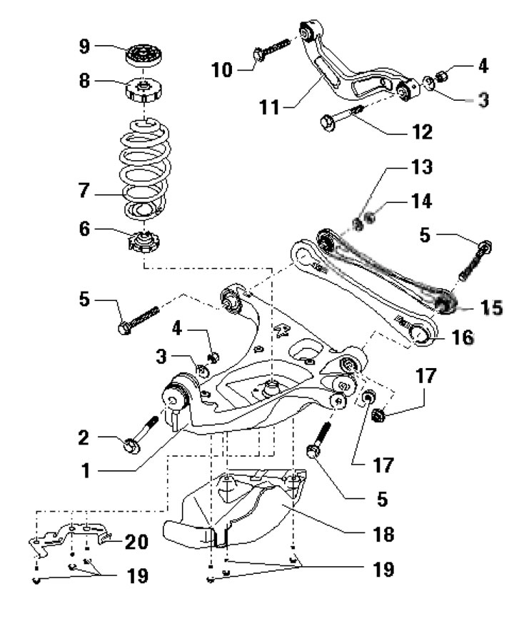
1.2s. Rear suspension rods 1. Trapezoidal row; 2, 12. Eccentric bolt; 3. Eccentric washer; 4. Self-locking nut, 95 Nm, subject to replacement; 5, 10. Bolt with washer, subject to replacement, 85 Nm, then tighten to an angle of 90°; 6. Lower spring seat; 7. Spring; 8. Upper spring seat; 9. Upper spring seat, only on models with heavy-duty suspension; 11. Transverse thrust; 13. Washer; 14. Self-locking nut, to be replaced, 85 Nm, then tighten to an angle of 90°; 15. Guide rod; 16. Stone protection, only on models with reinforced suspension; 17. Self-locking flange nut, subject to replacement; 18. Rock guard for traction 1, only on models with heavy-duty suspension; 19. Flange bolt, 25 Nm; 20. Parking brake cable bracket
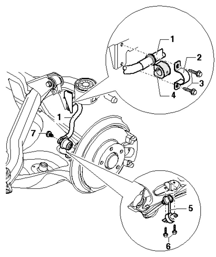
1.2d. Anti-roll bar 1. Stabilizer bar; 2. Clamp; 3, 6. Flange bolt, 25 Nm; 4. Bushing, subject to replacement; 5. Stabilizer link; 7. Flange bolt, 45 Nm
When working with aluminum suspension, the following should be observed:
- do not allow the suspension to come into contact with battery electrolyte;
- to clean the suspension, use only a stainless steel brush (not made of iron or brass);
- when grinding, cutting and welding, cover the suspension elements from sparks and scale;
- do not expose suspension components to temperatures above 80'C (exposure to paint booth temperature is acceptable).
The steering system consists of a steering wheel, a steering shaft, a rack-and-pinion steering gear, and a steering drive. The steering wheel with a built-in driver's front airbag is mounted on a shaft that transmits steering movements to the steering gear. To make driving easier, a power steering (PS) is used. The PS consists of a pump, a reservoir, hydraulic lines, and a radiator for the working fluid. The PS pump is driven through a multi-ribbed belt, sucks in PS fluid from the reservoir, and delivers it under pressure to the steering gear, where the power steering adjustment element is located (see illustrations 1.3a,b).
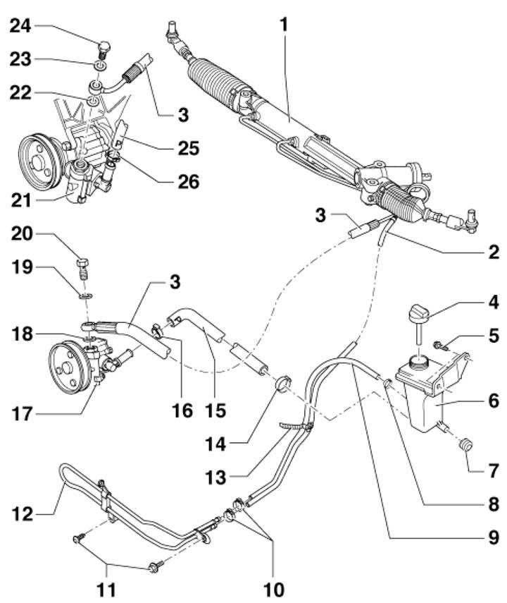
1.3a. Power Steering Components (4-cylinder models, 6-cylinder diesel models and 6-cylinder FSI models) 1. Steering gear assembly; 2. Return hose; 3. Expansion hose; 4. Cover with dipstick; 5. Bolt, 9 Nm; 6. Power steering fluid reservoir; 7. Rubber support; 8, 10. Hose clamp, subject to replacement; 9. Return hose; 11. Bolt, 10 Nm; 12. Cooling tube; 13. Tie; 14, 16. Hose clamp, subject to replacement; 15. Suction hose; 17. Power steering pump (6-cylinder models); 18, 19. Sealing ring, subject to replacement; 20, 24. Hollow bolt, 50 Nm; 21. Power steering pump (4-cylinder models); 22, 23. Sealing ring, subject to replacement; 25. Hose clamp, subject to replacement
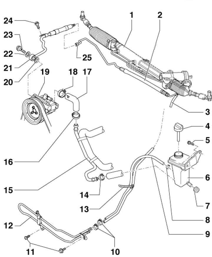
1.3b. Power Steering Components (6-cylinder MPI models)1. Steering gear assembly; 2. Expansion hose; 3. Return hose; 4. Cover with dipstick; 5. Bolt, 9 Nm; 6. Power steering fluid reservoir; 7. Rubber support; 8, 10. Hose clamp, subject to replacement; 9. Return hose; 11. Bolt, 10 Nm; 12. Cooling tube; 13. Tie; 14, 16. Hose clamp, subject to replacement; 15, 17. Suction hose; 18. Hose clamp, subject to replacement; 19. Power steering pump; 20, 22. Sealing ring, subject to replacement; 21. Expansion hose; 23. Hollow bolt, 50 Nm; 24. Bolt, 8 Nm; 25. Expansion hose connection, 40 Nm
When repairing or servicing suspension and steering components, problems often arise with loosening "stuck" bolts and nuts. The fasteners located under the bottom of the car are constantly exposed to external influences and over time they corrode and partially deteriorate. Using brute force to loosen such "stuck" fasteners is associated with the risk of damaging them. First, wet the element that cannot be loosened with a small amount of a special penetrating liquid (for example, WD-40), allowing it to soak into the rust layer well. Use a wire brush to remove external deposits from accessible areas of the threaded surfaces. Sometimes a sharp blow with a hammer on the nut through a drift helps to break up the rust filling the gaps between the turns of the threaded joint - try not to damage the threads as a result of the drift jumping off. Using a long handle when loosening "stuck" fasteners allows you to significantly increase the applied torque, but it should be remembered that the use of extensions in a set with ratchet-type drives is associated with the risk of failure of the return mechanism, as well as the possibility of injury. Self-locking nuts and fasteners damaged by corrosion or when removed during repairs must be replaced without fail.
Since most of the procedures described in this chapter are performed with the vehicle raised above the ground, you should take care in advance of options for securely fixing it in the raised position - prepare strong supports. To jack up the vehicle, use hydraulic jacks of the rolling type - remember that the onboard jack included in the standard package is intended only for temporary jacking of the vehicle when replacing a broken wheel. The hydraulic jack can also be used to hang up some suspension components when performing a particular procedure.
Attention: It is not permitted to carry out work under a vehicle that is held in a raised position only by means of jacks!
Welding and straightening of load-bearing suspension elements, as well as steering elements, is not permitted. Self-locking nuts and fasteners damaged by corrosion must be replaced during repair.
Chassis Identification
To identify the chassis, a sticker with vehicle data is used (see Chapter 1). It shows the PR numbers of the chassis (arrow in illustration 1.4), front suspension (A) and rear suspension (B).
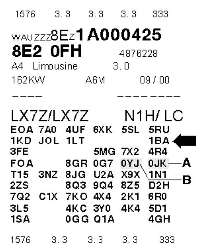
1.4. Chassis identification data