



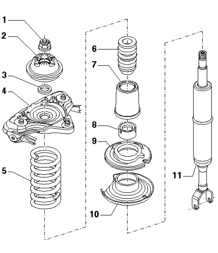
4.1. Suspension strut assembly parts 1. Flange nut, 50 Nm, subject to replacement; 2. Suspension strut bracket; 3. Washer; 4. Support bracket; 5. Spring; 6. Additional spring; 7. Protective sleeve; 8. Protective cap; 9. Lower spring seat; 10. Bottom spring plate; 11. Shock absorber
2. Remove the suspension strut (see Section 3) and secure it in a vice.
3. Compress the spring using the devices VAG1752/1 and VAG1752/4 shown in the illustration to release the upper spring plate. When compressing the spring, make sure that it is securely fastened in the puller. Loosen the flange nut using devices T1001/3, T1001/11 and T1001/7. Remove the strut parts and the compressed spring together with the puller.
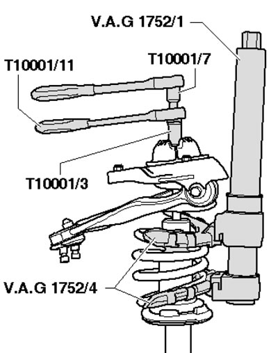
4.3. Spring compression
4. Remove the protective cap (1 in the illustration) and the lower spring seat (2), having previously marked the position of the seat relative to the shock absorber. Use a plastic hammer to knock off the spring plate (3) and remove it.
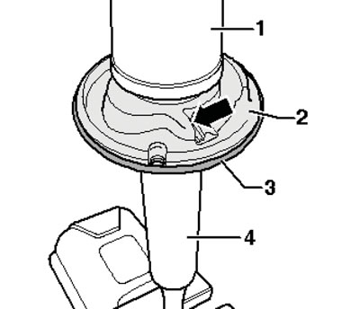
4.4. Removing the shock absorber
5. If a new shock absorber is being installed, transfer the marks from the old shock absorber that were made when it was pulled off. Install the spring plate according to the marks. Note the different installation positions for the left and right sides (see illustration). The flat edges on the spring plate must be away from the body.
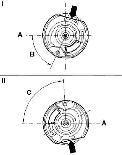
4.5. Spring plate installation positions A. Axis of the shock absorber and support arm mounting bolt; I. Left side: B=65°±2°; II. Right side: C - 87°±2°
6. Install the lower spring seat and protective cap. Position the compressed spring on the seat so that the edge of the spring enters the stop (arrow on the illustration). The maximum permissible deviation is 2°.
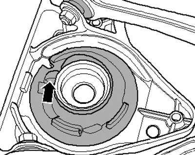
4.6. Stop on the lower spring seat
7. Fix the stand vertically and put the part removal on it. Make sure that the stopper of the upper seat is aligned with the cut of the upper coil of the spring, and tighten the flange nut.
8. Loosen the lower locking lever and rotate the upper plate until the stand is positioned as shown in the illustration. Make sure that the ends of the spring rest against the stoppers on the saddles and tighten the locking lever.
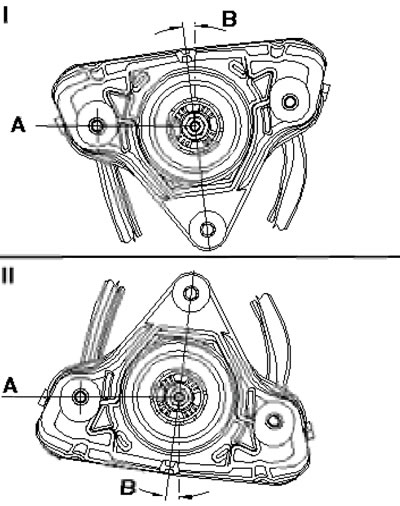
4.8. Installation position of the rack A. Axis of the shock absorber and support arm mounting bolt; B. 7°; I. Left side; II. Right side
9. Loosen the spring and remove the compression tools from it.