



2. Remove the wheel and secure the brake disc with one wheel bolt.
3. On models with headlight leveling adjustment, the suspension height sensor rod must be disconnected from the control arm before removing the left pillar (by opening the retainer).
4. Disconnect the ABS wiring from the bracket on the brake mechanism.
5. Separate the caliper from the anchor bracket and hang it on the body using a wire so that the brake hose is not twisted, kinked or stretched (see Chapter 9).
6. Use pliers to remove the retainer (1 in the illustration), then loosen the nut (2), unscrew the bolt and pull both rods up and out.
Note: The retainer must not be reused once removed. Do not attempt to enlarge the slots in the wheel bearing retainer with a chisel or similar tool.
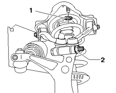
3.6. Bolt retainer (1) and coupling nut (2)
7. Cover the steering rod boot with a protective sleeve (see illustration) length (A) - 20-25 mm so that the cut is at the bottom. To prevent damage to the lower rods, support the suspension so that it does not drop too low.
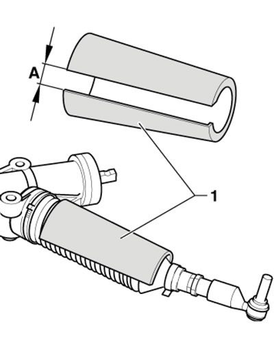
3.7. Steering rod boot protective sleeve
8. Unscrew the bolt (see illustration) suspension strut/control arm mounts. Tilt the wheel bearing carrier outward, separate the expansion tank supports and remove the gutter cover.
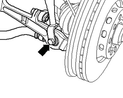
3.8. Lower suspension strut mounting bolt
9. Remove the bolt cover (see illustration).
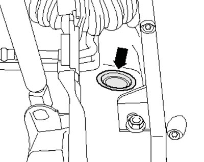
3.9. Bolt cover
10. Remove the top bolts (1 in the illustration) suspension strut mounts in the gutter and remove the strut with the support bracket. Do not damage the drive shaft boot.
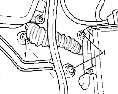
3.10. Upper suspension strut mounting bolts
11. Insert the strut with the support into the suspension cage and tighten the upper strut mounting bolts. Make sure the washers are seated correctly.
12. Insert the suspension strut fork into the rod and insert the bolt (see illustration 3.8) in front and tighten it.
13. Insert the pins of both upper rods into the wheel bearing housing and press them as deep as possible using pliers (see illustration 4.14 Chapter 8).
14. Install and tighten the new bolt (2 in the illustration) and a self-locking nut.
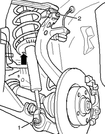
3.14. Installing the suspension strut
15. Further installation is carried out in the reverse order of dismantling the components.
The original version of the article is posted on the website: AudiManual.ru