
Repair Chevrolet Repair Toyota Repair Honda Repair AvtoVAZ Repair Mercedes-Benz Repair BMW Repair Opel
Home  |  Contacts  |  Sitemap  |    
English Русский
Български
Беларускі
Український
Српски
Hrvatski
Română
Polski
Slovenský
Magyar
AudiManual.ru


  • AUDI 80
  • AUDI 100
  • AUDI A3
  • AUDI A4
  • AUDI A6
  • AUDI A8
  • AUDI Q
  • OTHER
  • ARTICLES
B8 (2007-2015) B7 (2004-2008) B6 (2000-2006) B6 (2000-2006, petrol) B5 (1994-2001) B5 (1994-2001, petrol)

Removal and installation the front wheel bearing holder (Audi A4 B7)

  • Home
  • Audi A4
  • B7 (2004-2008)
  • Transmission
  • Drive shafts
  • Removal and installation the front wheel bearing holder
            0
Table of contents: Removal ↓ Installation ↓

Removal


1. Remove the central boot and unscrew the bolt securing the drive shaft to the hub while the vehicle is parked on its wheels.

2. Disconnect the ABS sensor wiring from the bracket on the wheel bearing housing.

3. On models with the HP-2 brake caliper, remove the bolt (2 in the illustration) and remove the brake pipe bracket. Unscrew the bolts (1) of the caliper and remove it. Install the brake pipe bracket in place, tighten the bolt (2). Secure the brake caliper to the body on the clamp so that the brake hose is not twisted, bent or stressed.
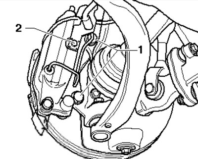
4.3. Removing the brake caliper

4.3. Removing the brake caliper


4. On all models, separate the brake caliper and secure it to the body using a clamp so that the brake hose is not twisted, kinked or under stress.

5. Unscrew the bolt (5 in the illustration) ABS sensor, unhook the sensor wire from the wheel bearing holder and remove the brake disc (see chapter 9).
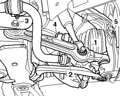
4.5. Bolt (5) for fixing the ABS sensor

4.5. Bolt (5) for fixing the ABS sensor


6. Remove the bolts (see illustration) and remove the heat shield.
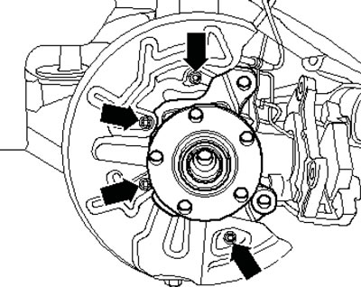
4.6. Fastening the heat shield

4.6. Fastening the heat shield


7. Unscrew the bolt with the washer (3 in the illustration) and bolt (4).
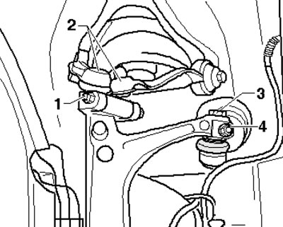
4.7. Bolt (3) for fastening the lever

4.7. Bolt (3) for fastening the lever


8. Pull or press the control arm downwards. Do not use a chisel or similar tool inserted between the steering rod (1 in the illustration) and boot, otherwise the boot may be damaged. Loosen the nut on the guide rod hinge stud until it is flush with the top of the thread. If necessary, hold the stud with a 4 mm wrench.
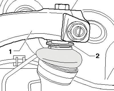
4.8. Steering rod (1) and boot (2) of the supporting arm

4.8. Steering rod (1) and boot (2) of the supporting arm


9. Press the guide rod stud out of the conical seat using the T40010 puller (see illustration), without damaging the drive shaft boot. The puller jaws should be parallel to each other when maximum force is applied to it.
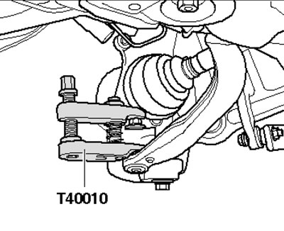
4.9. Separating the guide rod

4.9. Separating the guide rod


10. Press the bearing arm stud out of the conical seat using the T40010 puller (see illustration).
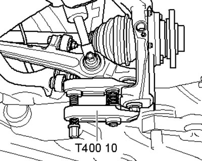
4.10. Separation of the support arm

4.10. Separation of the support arm


11. Give the nut (1 in illustration 4.7), unscrew the bolt and pull both upper rods (2) upwards.

Note: Do not attempt to enlarge the slots in the wheel bearing retainer with a chisel or similar tool. Tilt the wheel bearing retainer to the side and simultaneously pull the end of the drive shaft out of the hub. Tie the drive shaft to the body with wire. Remove the nut from the control arm stud and remove the wheel bearing retainer.


Installation


12. Slide the outer CV joint of the drive shaft into the hub and tighten the new bolt by hand.

13. Insert the control arm and guide rod pivot studs and tighten the new self-locking nuts, holding the studs from turning.

14. Insert the studs of both upper links into the wheel bearing holder and press them in as far as possible using pliers (see illustration).
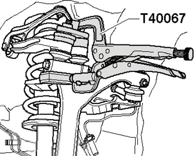
4.14. Pressing on the upper tie rod studs

4.14. Pressing on the upper tie rod studs


15. Tighten the new bolts (1 in illustration 4.7) and a self-locking nut.

16. Insert the control arm into the steering rod without using any tools.

17. Tighten the new self-locking nut (4 in illustration 4.7) and bolt (3)

18. Further installation is carried out in the reverse order of dismantling the components. Finally tighten the drive shaft mounting bolt only when the vehicle is standing on its wheels. After installation, check and, if necessary, adjust the front wheel alignment angles (see Chapter 10).
The article was checked by auto expert Timur Bazhenov
This article is available at russian, bulgarian, belarusian, ukrainian, serbian, croatian, romanian, polish, slovak, hungarian

Share information:
Previous articles
Audi A4 B7: Drive shafts
Next articles

Removal and installation the rear differential
Removal and installation of the cardan shaft and its components
Transmission line and wheel hubs — general information
Transmission line and wheel hubs — specifications
Removal and installation front drive shafts
Removal and installation rear drive shafts (AWD models)
Removal and installation the rear wheel hub (FWD models)/steel…


Similar articles on other Audi car models:
Front Wheel Hub Specifications Audi 80 B2 (1979-1986)
Front wheel drive Audi 100 C3 (1982-1990, petrol)
Removal and installation wheel bearing/hub assembly Audi A3 Type 8L (1996-2003)
Front wheel alignment angles Audi A6 C5 (1997-2004)
Front wheel alignment angles Audi A8 D2 (1994-2002)
Steering knuckle, wheel bearing module, shock absorber,… Audi Q5 Type 8R (2008-2017)
Removal and installation the front panel center holder Audi A2 (1999-2005)
Link to this page in different formats


Visitor comments

No comments yet


How much will 35 + 37 =


A4(B8, 2007-2015) 
  • General information
  • Operating instructions
  • Power unit
  • Petrol engines 1.8 l
  • Petrol engines 1.8/2.0 l
  • Petrol engines 3.0 l
  • Petrol engines 3.2 l
  • Fuel system (petrol)
  • Diesel engines 2.0 l (CA*)
  • Diesel engines 2.0 l (CJCB)
  • Diesel engines 2.7/3.0 l
  • Diesel engines 3.0 l
  • Fuel system (diesel)
  • Transmission
  • Manual gearbox 0B1
  • Manual gearbox 0B2
  • Manual gearbox 0B3
  • Manual gearbox 0B4
  • Automatic transmission 0B5
  • Automatic transmission 0B6
  • Automatic transmission 0AW
  • All-wheel drive system
  • Chassis
  • Front suspension
  • Rear suspension
  • Brake system
  • Steering system
  • Body
  • Exterior
  • Interior
  • Seats
  • Doors, locks and windows
  • Security system
  • Heating and air conditioning
  • Electrical equipment
  • Audio system
  • Power devices
  • Equipment and devices
  • Lighting and lamps
  • Electrical circuits
 
A4(B7, 2004-2008) 
  • General information
  • Introduction to manual
  • Troubleshooting
  • Operating instructions
  • Maintenance
  • Power unit
  • Petrol engines 2.0 (ALT)
  • Petrol engines 2.0 (TFSI)
  • Petrol engines 1.8 (MPI)
  • Diesel engines
  • Cooling system
  • Air conditioner
  • Fuel and exhaust system
  • Ignition system
  • Starting and charging
  • Transmission
  • Clutch
  • Manual gearbox
  • Automatic gearbox
  • Drive shafts
  • Chassis
  • Brake system
  • Front suspension
  • Rear suspension
  • Steering
  • Body
  • Exterior
  • Interior
  • Electrical equipment
  • Equipment and devices
  • Lighting and signaling
  • Windscreen wipers and washers
  • Electrical diagrams
  • Electrical diagrams (since 2007)
 
A4(B6, 2000-2006) 
  • General information
  • Vehicle Description
  • User manual
  • Maintenance
  • Power unit
  • Gasoline engine
  • Diesel engine
  • Lubrication system
  • Cooling system
  • Supply system
  • Injection system
  • Exhaust system
  • Ignition and control
  • Transmission
  • Gear box
  • Clutch and drive shafts
  • Chassis
  • Brake system
  • Car suspension
  • Steering
  • Body
  • Heating and ventilation
  • Exterior (external elements)
  • Interior (internal elements)
  • Electrical equipment
  • Power devices
  • Lighting and appliances
  • Electrical circuits
 
A4(B6, 2000-2006, petrol) 
  • General information
  • Introduction to the guide
  • Car care
  • Power unit
  • Engine repair
  • Lubrication system
  • Cooling system
  • Injection and control system
  • Ignition system
  • Power and exhaust system
  • Transmission
  • Clutch and drive shafts
  • Car gearbox
  • Chassis
  • Suspension and wheels
  • Steering
  • Brake system
  • Body
  • Interior
  • Exterior
  • Electrical equipment
  • Equipment and devices
  • Lighting and signaling
  • Power devices
  • Electrical circuits
 
A4(B5, 1994-2001) 
  • General information
  • Introduction to the guide
  • Car care
  • Maintenance (gasoline)
  • Maintenance (diesel)
  • Power unit
  • Gasoline engines
  • Diesel engines
  • Engine overhaul
  • Cooling system
  • Fuel injection (gasoline)
  • Fuel system (diesel)
  • Exhaust system
  • Ignition system
  • Transmission
  • Clutch
  • Mechanical gearbox
  • Automatic gearbox
  • Drive shafts
  • Chassis
  • Brake system
  • Car suspension
  • Steering
  • Body
  • Exterior
  • Interior
  • Doors, locks and windows
  • Heating and ventilation
  • Electrical equipment
  • Power devices
  • Equipment and devices
  • Electrical circuits
 
A4(B5, 1994-2001, petrol) 
  • General information
  • Vehicle description
  • Maintenance
  • Power unit
  • Engine repair
  • Turbocharging
  • Exhaust system
  • Cooling system
  • Ignition system
  • Fuel system
  • Motronic injection system
  • MPI and MPFI injection system
  • Transmission
  • Clutch
  • Gearbox and shafts
  • Chassis
  • Steering
  • Car suspension
  • Brake system
  • Wheels and tires
  • Body
  • Heating and ventilation
  • Body parts
  • Electrical equipment
  • Fuses and relays
  • Power devices
  • Lighting and lamps
  • Tools and devices
  • Electrical circuits
 
AudiManual.ru © 2017-2026 · Mobile version · Feedback · Sitemap: EN BG BY UA RS HR RO PL SK HU · Site search · News and articles
80 B2 · 80 B3 petrol · 80 B3 · 80 B4 · 100 C3 diesel · 100 C3 petrol · 100 C3 · 100 C4 petrol · 100 C4 · A3 Type 8L · A4 B5 petrol · A4 B5 · A4 B6 petrol · A4 B6 · A4 B7 · A4 B8 · A6 C4 · A6 C5 · A6 C5 Allroad · A8 D2 · Q5 Type 8R · Q7 Typ 4L · Audi A2 ·
This site uses cookies 🍪. Click the button to accept this fact.