



On AWD models, the rear differential is identified by its code designation and production date (1 in illustration 1.1), and also by name (2), - for example, 01 R. The code designation occupies the first three positions (for example, EXZ), followed by 2-digit designations of the date, month and year of production.
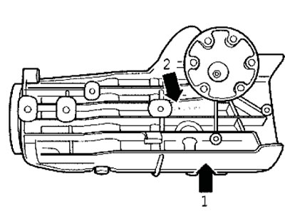
1.1 Rear Differential Identification Data
On FWD models, engine torque is transmitted to the front wheels via the AT/CVT/RCPT, differential and drive shafts. On AWD models, a transfer case is additionally installed on the rear side of the transmission, transmitting part of the torque via the propeller shaft, rear differential and rear drive shafts to the rear wheels.
The variable angle of inclination of the drive shafts is achieved by means of constant velocity joints (CV joints) placed in protective boots.
The installation details of the main components of the transmission line are shown in Illustrations 1.2 ai. The front differential of FWD models with manual transmission is shown in Illustration 6.3 b in Chapter 6.
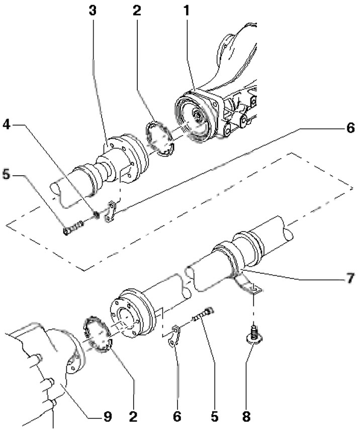
1.2a. Cardan shaft installation details 1. Rear differential; 2. Gasket, subject to replacement; 3. Cardan shaft assembly; 4. Balancing washer, if any; 5. Self-locking bolt, 55 Nm, must be replaced; 6. Locking plate; 7. Central bearing; 8. Bolt, 25 Nm; 9. Transmission
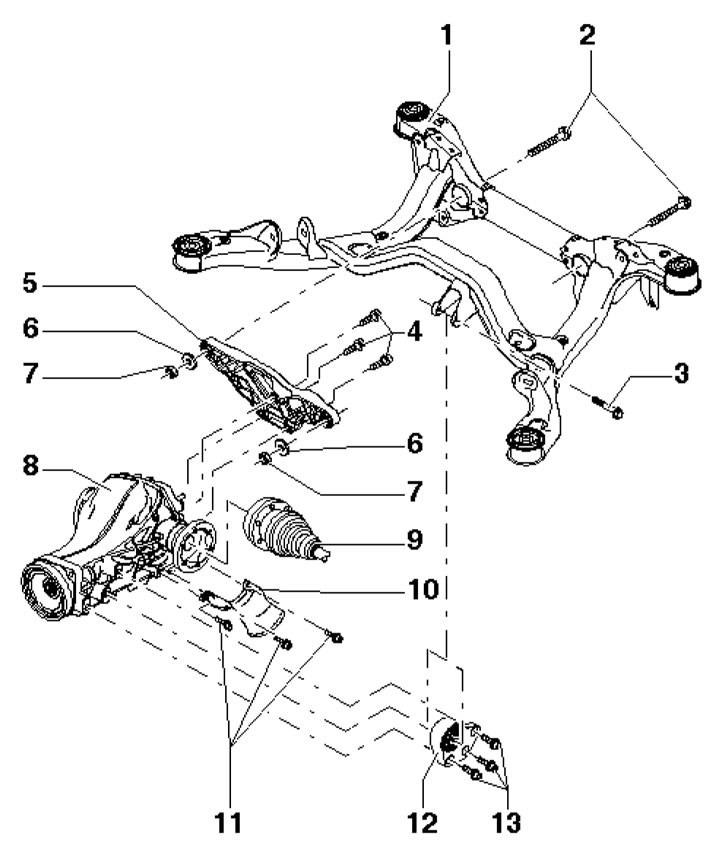
1.2b. Rear differential installation details 1. Rear subframe; 2. Bolt; 3. Bolt, 40 Nm; 4. Bolts, 40 Nm; 5. Rear crossmember; 6. Washer; 7. Self-locking nut, subject to replacement; 8. Rear differential; 9. Drive shaft; 10. Protective cover; 11. Bolts, 25 Nm; 12. Rear differential support; 13. Bolts, 40 Nm
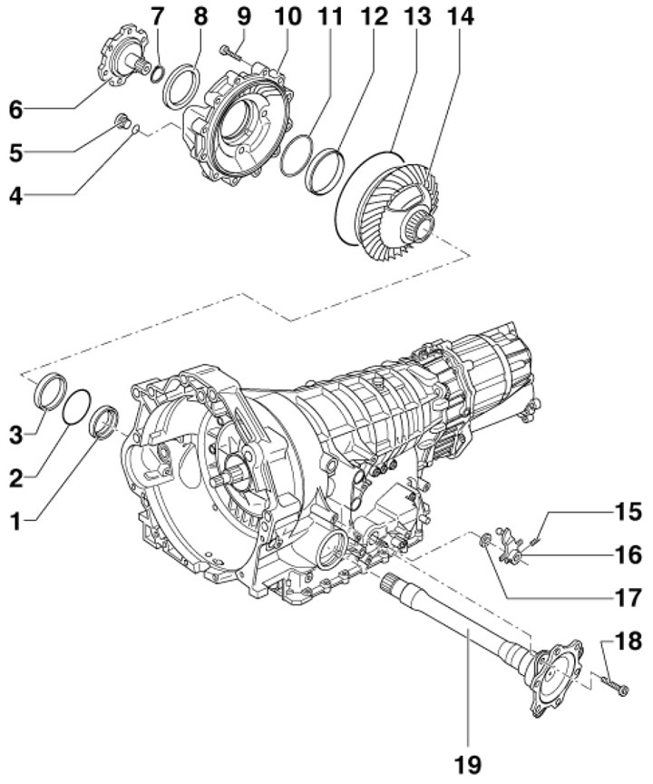
1.2s. Front differential installation details using AWD models with AT as an example 1. Seal; 2, 11. Adjusting washer; 3, 12. Outer race of tapered roller bearing; 4. Sealing ring, subject to replacement; 5. Threaded plug, 35 Nm, subject to replacement; 6. Right flange shaft; 7. Retaining ring; 8. Shaft seal 6; 9, 18. Bolt, 23 Nm; 10. Differential cover; 13. Cover sealing ring 10; 14. Differential; 15. Spring pin; 16. Selector shaft lever; 17. Selector shaft oil seal; 19. Left flange shaft
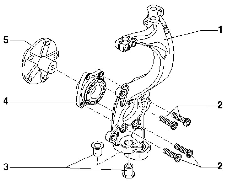
1.2d. Front wheel bearing installation details 1. Hub bearing housing; 2. Countersunk head bolts, 80 Nm, then tighten to 90° angle; 3. Bushings; 4. Ball hub bearing (is installed with a large diameter to the wheel hub); 5. Front wheel hub
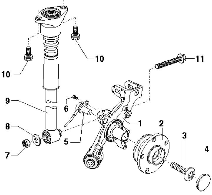
1.2e. Rear wheel hub installation details for FWD models 1. Hub holder; 2. Hub assembly, replaceable only as a complete unit; 3. Flange bolt, 200 Nm, then tighten to 180°, must be replaced; 4. Dust cover, subject to replacement; 5. VSS sensor; 6. Bolt, 10 Nm; 7. Self-locking nut, subject to replacement; 8. Washer; 9. Shock absorber; 10. Bolt with washer, 36 Nm; 11. Bolt with washer, 150 Nm, then tighten to 90° angle, subject to replacement
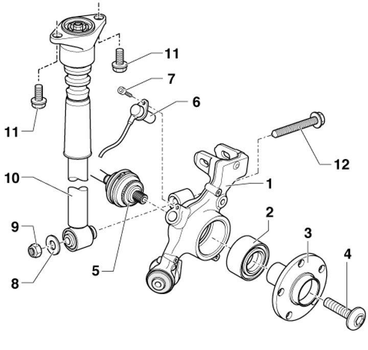
1.2f. Steel hub assembly for AWD models 1. Hub bearing housing; 2. Wheel bearing; 3. Rear wheel hub; 4. Flange bolt, 200 Nm, then tighten to 180°, must be replaced; 5. Drive shaft; 6. VSS sensor; 7. Bolt, 10 Nm; 8. Washer; 9. Self-locking nut, subject to replacement; 10. Shock absorber; 11. Bolt with washer, 36 Nm; 12. Bolt with washer, 150 Nm, then tighten to 90° angle, subject to replacement
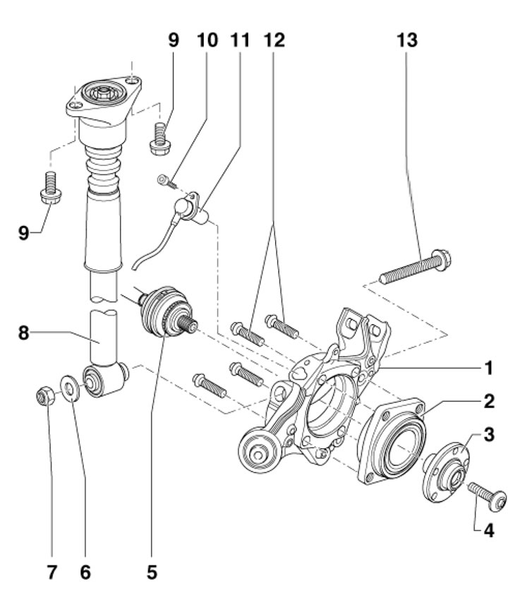
1.2g. Aluminum hub assembly for AWD models 1. Hub bearing housing; 2. Wheel bearing; 3. Rear wheel hub; 4. Flange bolt, 200 Nm, then tighten to 180°, must be replaced; 5. Drive shaft; 6. Washer; 7. Self-locking nut, subject to replacement; 8. Shock absorber; 9. Bolt with washer, 36 Nm; 11. VSS sensor; 12. Countersunk head bolts, 80 Nm, then tighten to 90°, must be replaced; 13. Bolt with washer, 150 Nm, then tighten to an angle of 90°, subject to replacement
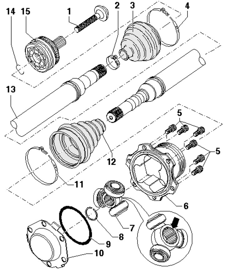
1.2h. Drive shaft with tripod inner CV joint 1. Bolt, subject to replacement; 2. Small clamp, subject to replacement; 3. CV joint boot 15; 4, 11. Large clamp, subject to replacement; 5. Bolts; 6. Inner CV joint housing; 7. Inner hinge with rollers (the chamfer faces the shaft splines); 8, 14. Retaining ring, subject to replacement; 9. Sealing ring, subject to replacement; 10. Cover, subject to replacement; 12. Inner CV joint boot; 13. Drive shaft; 15. Outer CV joint, replaced as an assembly
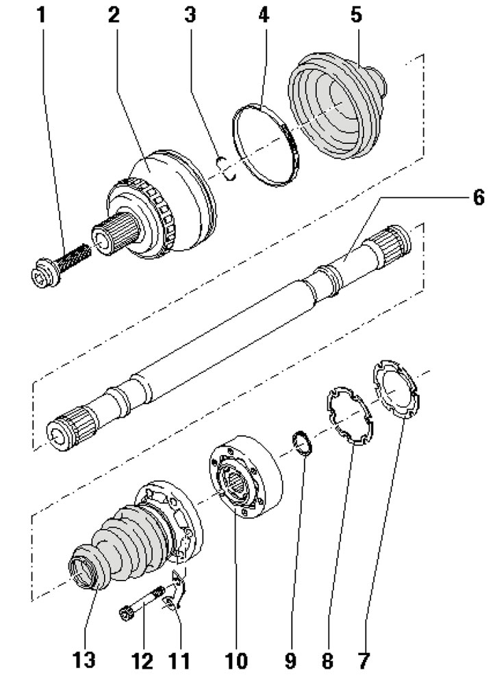
1.2i. Drive shaft with conventional internal CV joint 1. Bolt, subject to replacement; 2. Outer CV joint; 3, 9. Retaining ring, subject to replacement; 4. Large clamp, subject to replacement; 5. CV joint boot 2; 6. Drive shaft; 7. Cover, subject to replacement; 8. Gasket, subject to replacement; 10. Inner CV joint; 11. Locking plate; 12. Bolt; 13. CV joint boot 10 with cover
[The original article is located on the online resource: audimanual.ru]