



Table of contents: Section AT ↓ Automatic transmission clutch design ↓ Pinion gear ↓ Pinion gear ↓ Assembly of the main transmission AT ↓ AT parking gear ↓ Planetary assembly AT ↓ AT valve assembly ↓
Warning: Individual characteristics are also given in the text of the Chapter and, if their implementation is mandatory, are highlighted in bold
| General parameters | |
| Type | 4-speed (or 5-speed), all forward gears are synchronized. The main gear is located in the gearbox housing |
| Designation | 01M |
| Liquids used | |
| Automatic transmission | |
| Type | ATF ESSO EGL 71 141 or AUDI–ET No. G052 162 A2 (light yellow) |
| Volume | |
| When replacing | 3.0 l |
| Total | 5.3 l |
| Oil main gear of automatic transmission | 0.75 l, synthetic oil G052 162 A2…SAE 75W90 |
| Clutch oil Haldex models with all-wheel drive | 0.25 l clutch oil Haldex specification G 052 175 A1 |
| Tightening forces threaded connections | |
| Fastener tightening torques are given
in the text of the Chapter and in some illustrations*. *Highlighted in text in bold the tightening torques must be strictly observed; not highlighted in bold the efforts shown in font are only approximate | |
| Fastenings AT on the engine | |
| m10 bolts | 60 Nm |
| m12 bolts | 80 Nm |
| Converter rotation to the drive disk | 60 Nm |
| Starter to the transmission | 60 Nm |
| Left support bolt to the transmission | 25 Nm |
| Left support bolt to the bracket | 60 Nm |
| Front support bolt to the bracket | 60 Nm |
| Transmission shield bolt | 15 Nm |
| Drive shafts to AT flange | 45 Hm |
| Automatic transmission oil filler plug transmissions | 15 Nm |
| Oil drain plug haldex clutches for 4WD models | 15 Nm |
| Haldex clutch filler plug models with all-wheel drive | 30 Nm |
Section AT
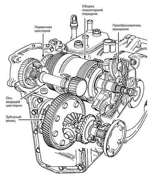
Automatic transmission clutch design
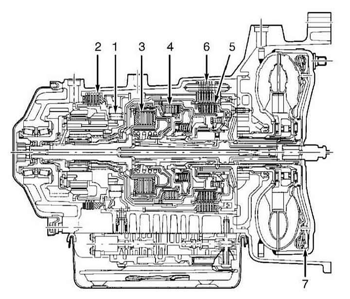
- 1 roller overrunning clutch
- 2 brake clutch reverse gear
- 3 4th gear feed clutch
- 4 feed clutch gear 1/3 gear
- 5 reverse gear feed clutch
- 6 brake clutch gear 2/4 gear
- 7 locking clutch of the rotation converter
Pinion gear
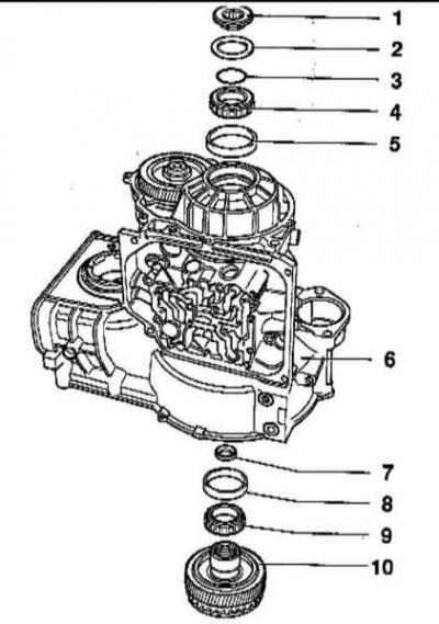
- 1 - socket head retainer
- 2 – disc washer
- 3 - adjusting washer
- 4 - inner race of tapered roller bearing
- 5 - outer race of tapered roller bearing
- 6 - transmission housing
- 7 - axial needle bearing
- 8 - outer race of tapered roller bearing
- 9 - inner race of tapered roller bearing
- 10 - leading gear
Pinion gear
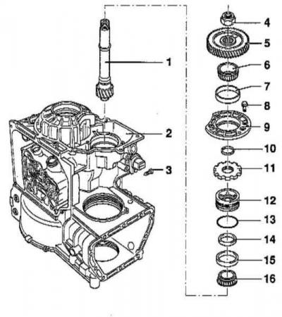
- 1 - retainer with socket head.
- 2 - transmission housing. Plate washer.
- 3 - screw
- 4 - hex nut
- 5 - driven gear
- 6 - inner race of tapered roller bearing
- 8 - bolt
- 9 - bearing cap
- 10 - adjusting washer
- 11 - Parking lock gear
- 12 thrust bearing ring
- 13 - sealing ring
- 14 - pinion seal
- 15 - outer race of tapered roller bearing
- 16 - inner race of tapered roller bearing
Assembly of the main transmission AT
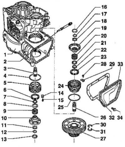
- 1 - transmission housing
- 2 - speedometer drive
- 3 - output shaft with drive flange
- 4 - sealing ring
- 5 - adjusting ring
- 6 - leading flange seal
- 7 - cone ring
- 8 - thrust washer
- 9 - compression spring
- 10 - leading flange
- 11 - disc washer
- 12 - retaining ring
- 13 - lid
- 14 - blocking element
- 15 - screw
- 16 - cover
- 17 - retaining ring
- 18 - disc washer
- 19 - drive flange
- 20 - compression spring
- 21 - thrust washer
- 22 - cone ring
- 23 - leading flange seal
- 24 - bearing housing
- 25 - sealing ring
- 26 - output shaft/drive flange
- 27 - differential
- 28 - screw
- 29 - blocking element
- 30 - retaining ring
- 31 - retaining ring
- 32 - sealing gasket
- 33 - cover
- 34 - screw
AT parking gear
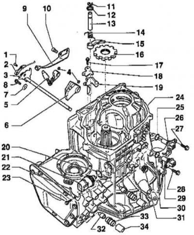
- 1 - bolt
- 2 - manual selection valve control
- 3 - selector shaft with selection segment
- 4 - spring finger
- 5 - connecting lever
- 6 - fixing segment
- 7 - lock washer
- 8 - bolt
- 9 - selection segment spring
- 10 - bolt
- 11 - sealing ring
- 12 - washer
- 13 - axis of the locking lever
- 14 - return spring
- 15 - locking lever
- 16 - Parking locking gear
- 17 - bolt
- 18 - thrust plate
- 19 - guide plate
- 20 - sealing ring
- 21 - Multifunctional transmission mode switch
- 22 - bracket
- 23 - bolt
- 24 - transmission housing
- 25 - sealing ring
- 26 - vehicle speed sensor
- 27 - bolt
- 28 - bolt
- 29 - Transmission vehicle speed sensor
- 30 - sealing ring
- 31 - sealing ring
- 32 - breather pipe
- 33 - breather
- 34 - breather cap
Planetary assembly AT
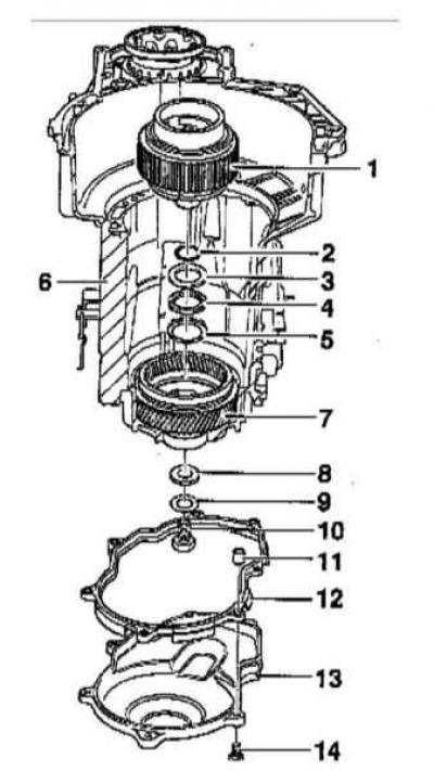
- 1 - holder
- 2 - sealing ring
- 3 - axial needle bearing washer
- 4 - axial needle bearing
- 5 - axial needle bearing washer
- 6 - bearing housing with installed driven gear
- 7 - driven gear
- 8 - holder adjusting washer
- 9 - washer
- 10 - bolt
- 11 - spacer sleeve
- 12 - sealing gasket
- 13 - lid
- 14 - bolt
AT valve assembly
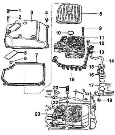
- 1 - plug
- 2 - overflow tube
- 3 - pallet
- 4 - bolt
- 5 - magnet
- 6 - spacer sleeve
- 7 - sealing gasket
- 8 - ATF screen
- 9 - bolt
- 10 - sealing gasket
- 11 - valve assembly housing
- 12 - bolt
- 13 - sealing ring
- 14 - conductive busbar with connector
- 15 - retainer
- 16 - pin electrical wiring connector
- 17 - connector lock
- 18 - nut
- 19 - Solenoid valve connectors
- 20 - Sealing plug
- 21 - sealing ring
- 22 - sealing ring
- 23 - actuator stem of manual selection valve
Instead of a manual transmission, the AUDI A3 can be equipped with a 4-speed automatic transmission (AT). When starting off, the AT functions as a regular clutch, and when driving, it shifts gears.
The main units of the AT are: torque converter, planetary gearbox and hydraulic or electronic control system. To switch to another gear ratio in the planetary gearbox, hydraulically driven disc brakes and disc clutch are used.
The torque converter functions like a hydraulic clutch. Its job is to provide clutch when starting off and changing gears.
The control of the pressure during switching is carried out by an electronic device instead of hydraulics used in a conventional manual transmission. Thus, there is more complete information for better control of the switching process, which makes it possible to select the optimal gear ratio depending on the vehicle operating mode and the driver's desire, which, in turn, improves the quality of the gear shifting process.
There are no manual programs "Economy" or "Sport". The control unit recognizes from the speed at which the pedal is pressed whether the driver wants to drive "sporty" or "economically" and controls the shift point accordingly. The shift control also takes into account the driving resistance, for example whether the car is moving uphill or downhill, whether there is a trailer and a headwind.
If there are any faults in the signal circuits of the sensors or electromagnetic valves, the system switches to the emergency driving program, and at the same time the faults are recorded in the fault memory. They can be read from the device memory later.
To evaluate the work and to correctly troubleshoot, appropriate experience with AT and qualifications are required.
Warning: Vehicles with automatic transmission may be towed for a distance of up to 50 km at a speed of no more than 50 km/h. When towing on a transporter, the front of the vehicle must be raised.
[The original article is available on the website: AUDIMANUAL]