
Table of contents: Removal and installation ↓ Rear axle lock ↓ Switching mechanism ↓ Gearbox oil level ↓
The gearbox (GPP) installed on the Quattro models is also installed on cars with a drive to the front two wheels, with the difference that an additional housing is installed on the ends of the GPP housing, which contains a special differential for the drive to the rear wheels. This housing can be removed together with the differential, without disassembling the GPP.
The following description refers to the operations associated with this process. To repair the gearbox and drive, it is necessary to use special devices and therefore you should not try to disassemble the gearbox, since without these devices it will be impossible to assemble it.
Note: As with two-wheel drive vehicles, different gearboxes are used. When installing a used gearbox, please pay attention to this.
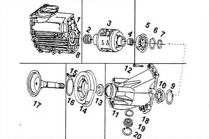
Assembly diagram of rear wheel drive components
1 Gearbox cover
2 Spring
3 Differential
4 Needle bearing
5 Ball bearing
6, 7 Retaining rings
8 Mounting sleeve
9 Retaining ring
10 Ball bearing for flange shaft
11 Differential cover
12 TORX head bolt, 25 Nm
13 Flange shaft seal
14 Vibration damper
15 TORX head bolt, 25 Nm
16 Retaining ring
17 Flange shaft
18 Sealing ring
19 Cap-plug.
20 Retaining ring
Removal and installation
Removal and installation of the gearbox is carried out in accordance with the instructions of the previous chapter. Additionally, it is necessary to unscrew the cardan shaft from the drive to the rear wheels (rear axle flange). It is necessary to observe the tightening torques, length and location of the bolts between the engine and the gearbox in accordance with the gearbox already described.
Removal and installation the housing from the differentials
The cover, i.e. the housing for the differential (11) can be removed together with the differential. The differential cannot be repaired, i.e. in case of breakage it is replaced with a new one.
When removing and installing, follow the installation diagram, observing the following conditions.
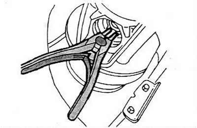
The shaft flange (17) is secured on the inside with a retaining ring, which is opened using special pliers for retaining rings. However, the retaining ring must not be opened too wide. After this, the shaft flange can be pulled out. After installation, the ring must be seated well on the bottom of the groove.
The needle bearing (4) must be removed using a suitable puller and a special hammer and installed using a suitable drift.
The ball bearing (o) is pressed out after placing a suitable plate from the differential, since the differential is pressed out through the ball bearing. A suitable piece of pipe is used for pressing.
The ball bearing (10) for the flange shaft is pressed out using a suitable piece of pipe from the outside inwards and pressed in from the opposite side.
The cover (11) must be lubricated with sealant AMV188 001 1 before installation on the housing.
Tighten the TORX head bolt (12) to 25 Nm. The bolt should be 42 mm long.
The seal for the flange shaft (13) is pulled out using a curved lever. A new seal is pressed in using a suitable rod until the outer surface is 2.0 mm below the cover surface.
Tighten the TORX head bolt (15) to 25 Nm. The bolt is 38 mm long.
Always replace the sealing ring (8) and lubricate it with grease before installation.
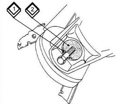
To remove the plug cap (19), screw the M8 bolt into the thread on the cap and pull out the cap (2). Before doing this, remove the retaining ring (1).
Rear axle lock
While early Quattro models were equipped with a mechanical differential lock on the rear wheels (pneumatically actuated), then in the A4 this is done with the help of an electronic differential lock, i.e. with the help of the EDS system. This device works in conjunction with the anti-lock braking system (ABS). Its operation is briefly described in the chapter "Brake system".
Switching mechanism
Everything that was said in the previous chapter about the shift mechanism of the five-speed gearbox of two-wheel drive vehicles also applies to Quattro models.
If you have difficulty changing gears, follow the instructions given in the previous chapter.
Gearbox oil level
To check the oil level and top it up, follow the instructions in the previous chapter.
(This article was copied from an online resource: «AUDImanual.ru»)