
Table of contents: Series 087 ↓ Series 089 ↓
Series 087
The accelerator control system must be adjusted so that when the throttle is closed, the gearshift lever is in the idle position. If the adjustment is incorrect, the gearshift speed will be too high at part throttle and the base pressure will be too high at idle.
Move the selector to position.
R Apply the parking brake.
Adjust the throttle control system to the idle position with the throttle valve closed.
Disconnect the clamps on the ball sockets and disconnect the rod from the rotary guide levers.
Disconnect the "cruise control" rods
Loosen the lock nut on the rod.
Position the traction lever approximately 1mm in front of the stopper.
Install the tie rod without tension. The ball socket should be turned so that it is level with the ball and the throttle lever should reach the stop.
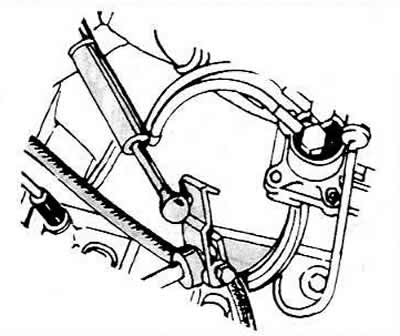
"Kickdown" device locking lever system
Note: Turbocharged engines have 2 thrusts.
Loosen the adjusting bolt to adjust the pushrod length (loosen the lock nut at the back).
Press the operating lever to the closed throttle position. The throttle valve should touch the idle stop.
Tighten the adjusting bolt to adjust the pushrod length.
Adjust the length of the pusher by moving the adjusting plate. The pusher should be installed on the operating lever without tension.
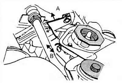
Gearbox pushrod adjustment
A Locking lever
In Gear Shift Lever
Remove the push rod from the operating lever.
Ask your assistant to press the gas pedal all the way down.
Press the operating lever to the kickdown stop.
Using pliers, pull the throttle cable back and secure it.
Check that the operating lever contacts the kickdown stop and adjust the pedal cable if necessary.
Install the pusher on the working lever and secure it.
Check the operation of the throttle lever.
Pull the throttle cable through the fully open throttle position to the kickdown stop.
The gearshift lever must touch the stopper.
The central spring should be compressed by approximately 8 mm.
Release the gas pedal and set the cruise control rod. The rod should be tension-free, adjust it if necessary.
Series 089
Remove the throttle control mechanism cover.
Loosen the 2 cable mounting nuts.
Turn the throttle valve to the fully open position and hold it in this position.
Using tool 3004 or similar, hold the throttle cable bracket at the wide open throttle position. Attach one end of the tool to the lower lever cable bracket. And the other end to the end of the bonnet gas strut.
Insert a bushing or similar piece measuring 17 mm between the gas pedal and its stopper.
The assistant should press the pedal down all the way.
Pull the throttle cable and install the locking clamp.
Pull the cable until you feel a force from the kickdown position of the transmission.
Tighten the nut on the cable side of the bracket, then tighten the nut on the hinge side of the bracket.
Remove the device.
The throttle lever should remain at the idle stop when the throttle is released.
Press the gas pedal to the fully open throttle position, but do not kickdown.
The force point for the fully open throttle position of the gas pedal should be approximately 19 mm from the pedal stop.
Press the gas pedal all the way down ("kickdown").
The spring between the cable brackets must be compressed.
For vehicles with cruise control, adjust the connecting rod by moving the ball end by 1-1.5 mm.
For vehicles with cruise control, the air conditioner switch should be engaged in the kickdown position and not engaged at wide open throttle. There should be approximately 2mm clearance between the switch and the cable bracket at wide open throttle (not kickdown).
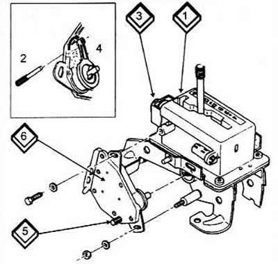
Adjusting the Starter Interlock Switch
1 Selector housing
2 Alignment pin (4mm)
3 Shift lock solenoid
4 Shift lever
5 Alignment pin
6 Starter interlock switch