
Table of contents: System operation ↓ Adjusting the system ↓
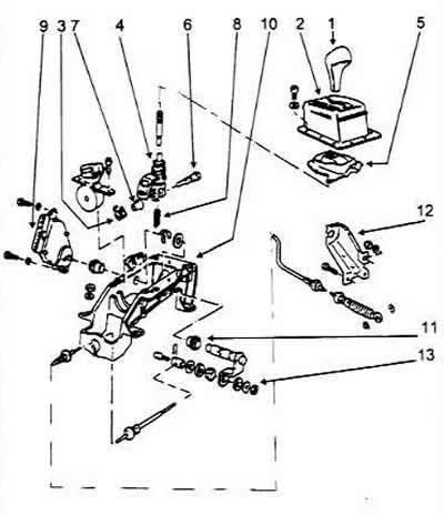
The device of the shift lever of the Shiftlock II automatic transmission system
1 Selector lever handle
2 Selector lever bracket
3 Torsion spring
4 Selector lever
5 Case
6 Guide pin
7 Bushing
8 Compression ring
9 Selector lever switch
10 Fastening
11 Bushing
12 Selector cable bracket
13 Gear shift lever
All vehicles with automatic transmissions are equipped with a shift-lock control system. The system must be adjusted correctly to ensure that the transmission shifts fully in each position. If it does not, the transmission may only shift partially in a certain range, which will cause damage due to slippage. Incorrect adjustment may also make it impossible to shift into or out of the P range.
The control system is designed to make it impossible to shift from P or N range unless certain conditions are met. The system is highly dependent on the correct operation or condition of fuse S12, the brake light switch circuit, the interior light relay control unit, the driver's door switch circuit and the vehicle speed signal.
System operation
When the ignition is switched on, the selector lever cannot be shifted from position P or N unless the brake pedal is depressed. At speeds below 6 km/h, when shifting to position N, the lever must be held in position N for one second unless the brake pedal is depressed. At speeds above 6 km/h, the selector lever should not be held.
Adjusting the system
Adjust the solenoid switch by inserting a 1 mm thick feeler gauge between the selector lever and the switch. With the lever in the R position, press the solenoid against the feeler gauge and tighten to 9 Nm.
Center the lower fork connection hole and apply voltage to the switch. The solenoid pin will lock the fork part.
Install the shift lever housing so that the selector lever is in position N relative to the housing.
Place the shift lever with the 4mm alignment pin through the housing hole.
Shift the selector lever to position N. Remove the alignment pin. Check for proper operation.
If the shift lever does not operate properly, it may be necessary to have the electronic control system checked.