
Removal
1. Place chocks under the rear wheels, apply the handbrake, raise the front of the car and install safety stands.
2. Remove both front wheels. When removing the wheels, tighten a wheel mounting bolt into each hub to prevent the brake disc from turning on the hub.
3. Loosen the mounting bolts and remove the lower engine protective cover.
4. As described in the chapter 2A or 2B, transfer the weight of the engine to the hoist by attaching it to the rear eye.
5. On vehicles equipped with xenon headlights, disconnect the sensor link from the front lower arm as described in chapter 12.
6. Carefully remove the ABS wheel sensor.
7. As described in paragraph 6, disconnect both vertical stabilizer links from the lower arms.
8. Disconnect the inner ends of both lower arms from the subframe as described in paragraph 5. To do this, you will have to disconnect the rear corners of the subframe from the body and lower them slightly to remove the lever bolt.
9. Disconnect the lower ends of both suspension struts from the front lower control arms as described in paragraph 3.
10. Disconnect the inner ends of both front lower arms from the subframe as described in paragraph 5.
11. Hang the steering knuckle, suspension strut and control arms inside the arch with wire to avoid putting stress on the bushings and joints.
12. Make sure that the power unit is securely fastened to the hoist, and remove the left and right gearbox supports from the subframe.
13. Unscrew the two subframe mounting bolts, which are located behind the stabilizer clamp brackets.
14. Loosen the four subframe mounting bolts installed in front of the stabilizer clamp brackets until you can release the subframe from the supports. Do not completely unscrew the bolts.
15. Carefully lower the subframe and remove it from under the vehicle.
Repair
16. Replacing the subframe bushings requires the use of a hydraulic press and a set of specially treated mandrels. It is not recommended to make mandrels yourself - the supports are easily damaged. Contact your dealer for help.
Installation
Note: All mounting nuts and bolts are replaceable.
17. Position the subframe in place and align the front mounts with their respective brackets. Install the new front mount mounting bolts, but do not tighten them at this stage.
18. Attach the gearbox supports to the subframe.
19. Attach the lower end of the suspension strut to the front lower arm as described in paragraph 3. Attach both lower arms to the subframe as described in paragraph 5. Do not fully tighten the bolts and nuts at this stage of installation.
20. Secure the vehicle level sensor link to the lower arm as described in chapter 12 (if xenon headlights are installed).
21. Select two pieces of wooden folder approximately 15 mm in diameter and 150 mm long. Working under the wheel arches, pass the bushings through the centering holes in the front corners of the subframe. Adjust the position of the subframe so that the sticks pass through all three holes on both sides (Fig. 7.21).
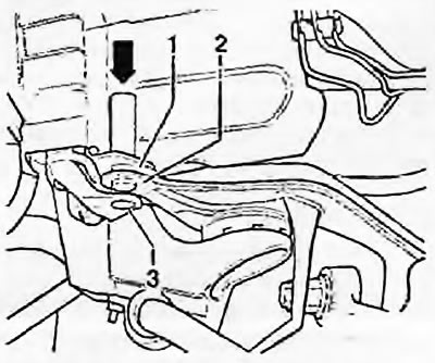
Fig. 7.21. Insert the wooden block (indicated by the arrow) through three holes in the front corners of the subframe: 1. Bracket (upper); 2. Subframe; 3. Bracket (lower)
22. Install the mounting brackets in the rear corners of the subframe, insert new bracket mounting bolts and tighten them slightly. After installing the brackets, insert new subframe mounting bolts and also tighten them slightly.
23. Disconnect the hoist and tighten the subframe and suspension mounting bolts in the order described below.
24. Tighten the four main subframe mounting bolts to the specified torques in two stages (Fig. 7.24).
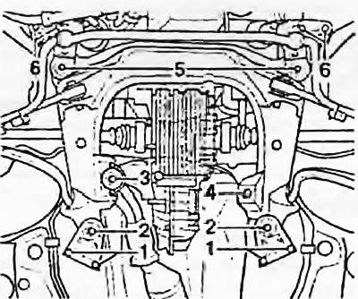
Fig. 7.24. Subframe mounting parts: 1. Rear mounting bracket bolts; 2. Main mounting bolts; 3. Gearbox support bolts; 4. Gearbox support bolts; 5. Main mounting bolts; 6. Front mounting bracket bolts
25. Tighten the four front subframe mounting bolts to the specified torques
26. Tighten the four rear subframe mounting bolts to the specified torques.
27. Tighten the gearbox mount mounting bolts to the specified torques as described in Chapter 7A or 7B.
28. Tighten the front and rear lower control arm inner mounting bolts to the specified torques as described in paragraph 5.
29. Install the vertical stabilizer links as described paragraph 6. Use new nuts for fastening and tighten them to the specified torque.
30. Tighten the strut-to-lower front arm mounting nuts to the specified torque as described in paragraph 4.
31. Secure the ABS wheel sensor wiring as described in paragraph 19 of chapter 9.
32. Install the lower protective cover. Install the wheels. Lower the vehicle and tighten the wheel mounting bolts to the specified torque.
33. Finally, weld and adjust the front wheel alignment angles as soon as possible.