
Table of contents: Front and rear upper control arms ↓ Front lower control arm ↓
Front and rear upper control arms
Note: Late model vehicles with sport or heavy duty suspensions have a bump stop above the rear wishbone. In addition, the upper rear control arm on all models since 1997 has a bump stop. When replacing the rear control arm, a similar arm is installed in place of the previous design.
Removal
1. Place chocks under the rear wheels, apply the handbrake and raise the front of the car. Install safety stands. Remove the corresponding wheel.
2. When removing the wheel, tighten the bolt that secures it into the hub so that the brake disc does not turn on it.
3. On vehicles with xenon lamps, disconnect the control rod from the front lower arm as described in chapter 12.
4. Carefully remove the ABS wheel sensor.
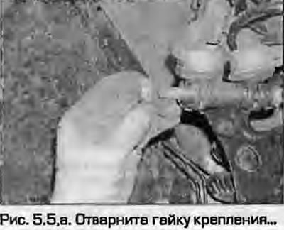
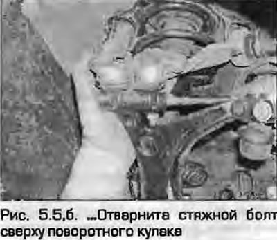
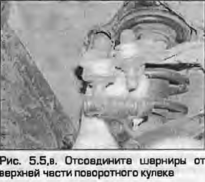
5. Unscrew the fastening nut, remove the clamping bolt from the upper part of the steering knuckle. Separate the ball joints of the upper arms from the steering knuckle. Do not spread the gap with any screwdrivers or chisels to make it easier to remove the support pins (fig. 5.5, a-c). Try not to damage the covers.
 |
 |
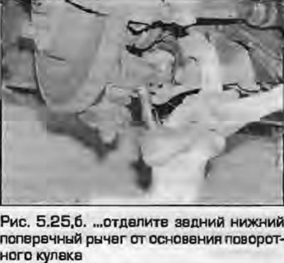
6. Loosen the mounting nut and separate the rear lower arm from the base of the steering knuckle using a ball joint puller (do not damage the case). This will allow the lower bolt to be removed from the front lower control arm.
7. Loosen the nut and remove the lower suspension strut mounting bolt from the front arm (see paragraph 4).
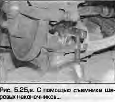
8. The upper arm bracket mounting bolts are located on the butt at the rear of the ends - try not to damage the rubber boot (Fig. 5.25).
 |
 |
26. Unscrew the nut from the bolt on the inner side of the lever. To remove the bolt, you need to slightly lower the subframe corner. To do this, unscrew the two plate mounting bolts and unscrew the subframe mounting bolt. Note that the bolt is threaded through two holes in the subframe.
27. Lower the subframe slightly, remove the inner wishbone mounting bolt and remove the wishbone from the vehicle.
Repair
28. Thoroughly clean the lever and the area around the supports, removing all traces of dirt and anaerobic sealant. Check for cracks or other signs of damage, paying particular attention to the inner bushing and the hinge. Note that the inner bushing is hydraulic and a leak from it indicates that the bushing is damaged and requires replacement. The hinge is an integral part of the lever and is not supplied separately as spare parts. If the lever or hinge is damaged, the entire unit is replaced.
29. Replacing the inner bushing requires the use of a hydraulic press and is best left to the specialists at a dealership service center or a suitably equipped garage. If such equipment is available, press in the tube using only its outer edges. The bushing is pressed in such a way that the projections are parallel to the central axis of the lever.
Installation
30. Installation - reverse procedure. Please note the following:
- a) Use only new wishbone and subframe mounting bolts and nuts.
- b) Perform the final tightening of the inner wishbone mounting bolt after the vehicle has been lowered onto its wheels.
- c) Pass the inner wishbone mounting bolt through the two holes in the subframe.
- d) Tighten threaded connections to the specified torques.
Front lower control arm
Removal
31. Place chocks under the rear wheels, apply the handbrake and raise the front of the car. Install safety stands. Remove the corresponding wheel.
32. When removing the wheel, tighten the bolt that secures it into the hub so that the brake disc does not turn on it.
33. On vehicles with xenon headlights, disconnect the sensor drive rod from the front lower arm as described in chapter 12.
34. Loosen the mounting nut and separate the arm from the base of the steering knuckle using a ball joint puller (try not to damage the case).
35. Loosen the nut and remove the lower suspension strut mounting bolt from the arm.
36. Loosen the mounting nut and disconnect the vertical stabilizer bar link from the arm as described in paragraph 6.
37. Loosen the nut and remove the inner arm mounting bolt. Remove the arm from the vehicle. Note that the bolt passes through two holes in the subframe.
Repair
38. Thoroughly clean the lever and the area around the supports, removing all traces of dirt and anaerobic sealant. Check for cracks or other signs of damage, paying particular attention to the inner bushing and the hinge. The hinge is an integral part of the lever and is not supplied separately as spare parts. If the lever or hinge is damaged, replace the entire unit.
39. Replacing the inner bushing requires the use of a hydraulic press and it is better to entrust this work to specialists at a dealership service center or a suitably equipped garage. If you have such equipment, press in the tube, relying only on its outer edges. The bushing is pressed in so that the projections are parallel to the central axis of the lever.
Installation
40. Installation - reverse procedure. Please note the following:
- a) Use new bolts and nuts for the i ioi yoke and strut mounting bracket.
- b) Perform the final tightening of the inner bolt securing the transverse arm and vertical stabilizer link after lowering the vehicle onto its wheels, so as not to damage the bushings.
- c) Pass the inner wishbone mounting bolt through the two holes in the subframe.
- d) Tighten threaded connections to the specified torques.
(The original article is available on the online resource: «audimanual.ru»)