
Table of contents: Replacing the front shock absorbers ↓ Removal the front shock absorber… ↓ Removal the front wheel hub bearing ↓
Replacing the front shock absorbers
Many elements of the front wheel suspension can be removed and reinstalled independently. However, such work still requires tools from the workshop. Damaged suspension parts should never be straightened, much less welded; they must be replaced with new ones.
The shock absorbers at the front of the Audi 100 can be replaced without removing the spring or the entire shock absorber strut. This would be ingeniously simple if it were not for the need for a special tool 2069 to attach the shock absorber. Since this tool is only available in workshops, you can use a socket wrench, which has an external hexagon of 33.5 mm in width. If you do not find such a wrench, in an emergency you can turn the protective cuff so that the nut on the wing side can be unscrewed with a large pipe wrench. To release the piston rod nut at the top of the shock absorber strut, a special tool is used in car workshops to tighten it with the same torque. In exceptional cases, you can use a ring spanner and your own intuition.
Important: The car must be on all 4 wheels while these operations are being carried out and must not move under any circumstances! Apply the parking brake!
Remove the plastic cover from the shock absorber strut.
Mark the location of the shock absorber bearing (see fig. top left).
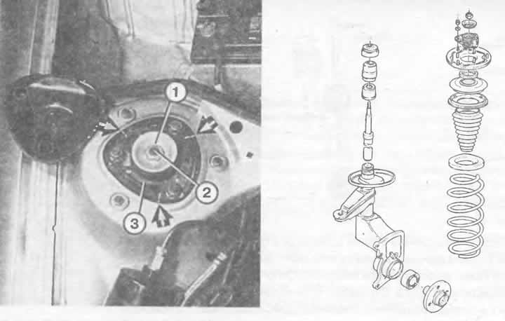
Left: Replacing the front shock absorber. The numbers indicate:
1. Piston rod nut 22 mm;
2. Shock absorber piston rod with 7 mm hexagon socket;
3. Shock absorber strut bearing. The arrows point to the markings provided, which indicate the installation position of the upper shock absorber strut bearing. Only if the markings match after assembling the shock absorber strut, then no wheel alignment adjustment will be required.
Right: The figure shows all the components of the front shock absorber.
Unscrew the piston rod nut size 22; hold the piston rod with a 7mm Allen key.
Remove the bearing by loosening the 3 x 13mm nuts.
Remove the rubber buffer from the piston rod.
Adjust the steering so that the piston rod is directed in the middle towards the bearing plate. To fix it, clamp a piece of wood between the spring and the wheel arch.
Remove the disc washer from the piston rod.
Grasp between the coils of the spring and unscrew the corrugated cover.
Use special tool 2069 to loosen the shock absorber cartridge fastening nut, which is deeply seated in the shock absorber strut (or as already described) and pull the cartridge up.
Do not move the car with the cartridge removed! Otherwise, the spring may jump out! There is a high risk of an accident!
Assembly: install the shock absorber.
Tighten the threaded cap using special tool 2069 to 24 Nm.
Install the shock strut bearing (30 Nm; use new self-locking nuts. Place a disk-washer). Please note that the labels on the shock absorber bearing match the labels on the shock absorber itself.
Otherwise, tighten the nut on the shock absorber rod to a torque of 60 Nm (use new self-locking nuts) with a socket wrench.
Removal the front shock absorber strut 4- and 5-cylinder engines
The procedure for 4- and 5-cylinder engines is described here. In 6-cylinder engines, the subframe must also be removed (also called a bracket for mounted units). To do this, you need to fix it with a leveling device - in our opinion, this is a very difficult job for an amateur.
Purchase new self-locking nuts for the independent suspension joint.
Then you will need a new clamp bolt and one screw for the drive shaft (outside).
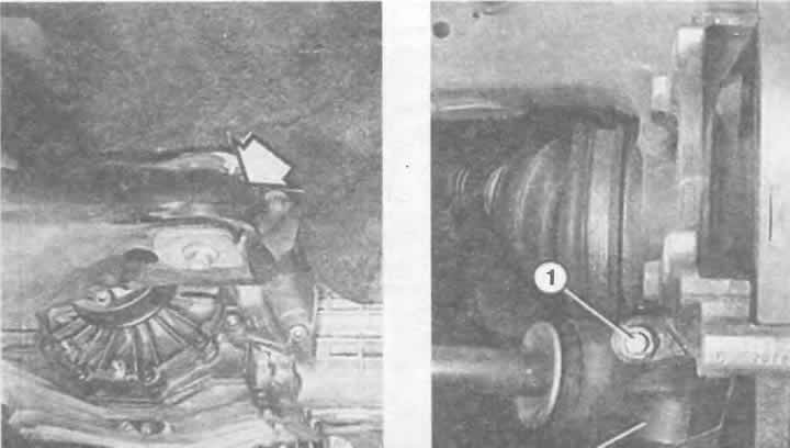
With the vehicle on the ground, loosen the central mounting bolt of the drive shaft in the wheel hub (in the middle of the wheel).
Raise the car evenly from the front so that the stabilizer is not loaded. Ensure that the car is secured.
Remove the wheel.
Disconnect the stabilizer link from both shock absorber struts and press the stabilizer upwards.
Remove the lower trim of the engine compartment (chapter "Body elements").
Unscrew the stabilizer bearing shells on the right and left sides of the body.
Disconnect the disc brake caliper and secure it to the body using wire - the brake drive line remains connected.
Remove the axle joint clamp bolt at the very bottom of the shock absorber.
Use a pry bar to pull the hinge pin out of the shock absorber strut. This will separate the shock absorber strut and the suspension arm. Do not damage the leading cuff (drive) shaft.
Important: In this case, do not under any circumstances widen the slot in the wheel hub bearing housing, for example with a screwdriver. Instead, use a rust remover.
Disconnect the tie rod joint (see a little earlier in this chapter).
Unscrew the three nuts on the shock absorber strut cup. While doing this, hold the shock absorber strut from below.
Pull the shock absorber strut downwards and at the same time remove it completely from the drive shaft.
Prevent the drive shaft from falling down (bearing damage possible). Tie with wire.
What you need to pay attention to when installing the drive shaft is described in the chapter "Transmission and final drive".
Screw on the outer bearing of the control arm (new bolt and nut) The bolt should fit into the groove of the inserted control arm bearing pin.
Other tightening torques: upper mounting nut (on the glass) shock absorber strut: 30 Nm, tie rod nut: 60 Nm.
If the same shock absorber strut is installed and the bolts connecting the wheel hub bearing housing and the shock absorber strut remain tightened at all times, then there is no need to adjust the wheel alignment angles.
Replacement of the transverse suspension arm with a hinge. Cars with 4- and 5-cylinder engines.
The hinge and the wishbone are a single part in the Audi-100. Anyone who buys a replacement unit should note that this is a version with an already pressed-in inner suspension balancer bracket (wishbone bearing). It is also sold separately for subsequent pressing in, which will require a press available in the auto repair shop. Below is a description of the removal and assembly of the transverse suspension arm for cars with 4- and 5-cylinder engines. In cars with 6-cylinder engines, it is necessary to additionally remove the subframe (bracket for mounted units). To do this, the engine must be secured with a leveling device - this is a very difficult job for an amateur.
Purchase a new self-locking nut and a new clamp bolt for the independent suspension joint.
Raise the car evenly from the front so that the stabilizer is not loaded. Ensure that the car is secured.
Remove the lower trim of the engine compartment.
Unscrew the stabilizer bearing shells on the right and left.
Remove the suspension joint clamp bolt at the very bottom of the shock absorber.
Use a crowbar to push out the pivot pin of the independent suspension at the shock absorber strut. This will separate the shock absorber strut and the transverse suspension arm. Do not damage the cuff of the drive shaft.
Left: On the inside, the wishbone is secured to the subframe with a rubber-metal support (arrow). After removing the bolts visible in the illustration, the bearing shells should be removed from the screw hole.
Right: The wishbone (2) at the front axle is connected to the shock absorber housing via the independent suspension joint. The bolted connection marked "1" holds the wishbone support in the shock absorber. To remove, loosen the nut and remove the bolt. The shock absorber spline must not be widened when removing the independent suspension joint pin.
Important: When removing the yoke pin, never widen the slot in the wheel bearing housing, for example with a screwdriver. Use a rust remover instead.
Unscrew the fastening nut at the bottom of the lower transverse control arm.
Remove the bearing sleeve from the threaded hole.
Disconnect the stabilizer mount and the suspension wishbone from the subframe and remove.
Installation: Strengthen the wishbone and align.
Install the inner bearing sleeve.
Tighten the new bolt for the inner wishbone bearing. Tightening torque: 110 Nm, and finally turn it another 90°.
Screw in the wishbone cross bearing (new bolt and nut). The bolt must enter the groove of the inserted pin of the wishbone bearing (65 Nm).
Screw on the bearing stabilizer on the left and right (105 Nm).
Install the car on wheels (put on the ground) and only now tighten the nuts on the back of the stabilizer (stabilizer bar to wishbone connection). Tightening torque: 120 Nm, and finally turn another 90°.
Have your wheel alignment checked at a car repair shop.
Removal the front wheel hub bearing
The wheel hub bearing is pressed into the housing with its outer rings, and the wheel hub is pressed into the inner ring. A new wheel hub bearing should never be hammered into place, otherwise you will "install" the next damage together with the bearing. Therefore, it is better to remove only the shock absorber strut itself and disconnect the brake disc and casing. And entrust the actual removal and installation of the bearing to a workshop.