
Table of contents: Drive shafts ↓ Removal the front drive shaft ↓ Removal the front drive shaft ↓ Removal the rear drive shaft ↓ Removal the outer hinge. All models ↓ Removal the internal hinge.… ↓ Removal the inner joint. "Tripod"… ↓
Drive shafts
Usually there are no problems with drive shafts. Their service life, of course, depends on the driving style. Abrupt starts with the front wheels turned out and starting off with slipping lead to premature failure of the joints.
Drive shaft joints usually suddenly show signs of malfunction, which, however, may soon disappear again completely. The "quiet phase" can last for many days or kilometers.
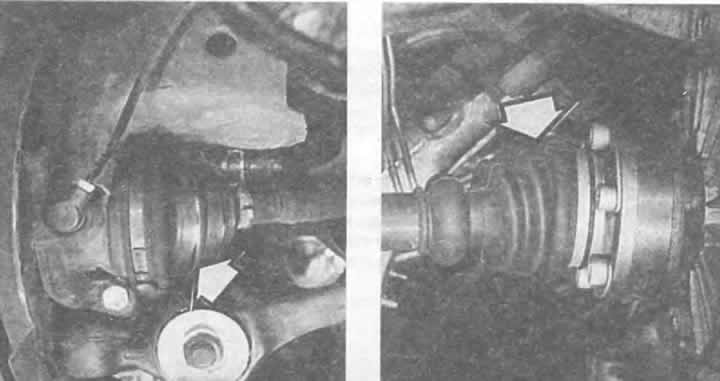
The seals (arrows) on the cardan joints of both drive shafts must not have cracks or other damage. Water and dirt are dangerous for the cardan joint.
Typical are rhythmic beating or knocking noises when pressing the accelerator pedal or when driving in forced idle mode (coasting). If the noise changes depending on the steering wheel turn, then most likely the outer joint is faulty (from the wheel side).
Vibrations and shaking of the steering wheel when the wheels are turned also indicate a faulty outer joint.
Removal the front drive shaft
You will need a new hex bolt with a locking element for the driveshaft in the outer wheel hub, as well as a sealing gasket for the inner joint of the shaft (no gasket required for 6-cylinder engine with manual and automatic transmissions).
Remove the wheel cap and loosen the wheel bolts.
Loosen the hex bolt in the wheel hub; for this, the Audi must be fixed.
Raise the car from the front and secure it and remove the wheel.
If present, remove the gearbox input shaft guard.
On models with ABS, pull the speed sensor back slightly.
Remove the socket head cap screws securing the shaft to the gearbox.
Press the cardan shaft away from the gearbox flange.
To remove the shaft, unscrew the steering gear accordingly.
Installation: Install a new sealing gasket on the inner homokinetic joint.
First insert the shaft from the wheel side. Then cross-tighten the fastening bolts on the drive flange from the gearbox side (M8 bolts: 45 Nm; m10 bolts: 80 Nm). Don't forget the sealing gaskets for the homokinetic joints!
Lower the vehicle, block the wheels. Tighten the new wheel hub bolts as follows:
Bolt M16x1.5: tighten to 200 Nm and finally tighten another ¼ turn (90°).
Tighten the nuts on the stabilizer connecting rod to a torque of 20 Nm.
On models with ABS, manually push the speed sensor all the way in.
Removal the front drive shaft
You will need a new hex bolt with a locking element for the outer joint of the drive shaft, as well as a sealing gasket for the inner joint of the shaft (gasket only for models with 5- and 6-cylinder engines)
Remove the wheel cap and loosen the wheel bolts.
Loosen the hex bolt in the wheel hub; for this, the Audi must be fixed.
Raise the car from the front and secure it and remove the wheel.
If present, remove the gearbox input shaft guard.
On models with ABS, pull the speed sensor back slightly.
Remove the socket head cap screws securing the shaft to the gearbox.
Press the cardan shaft away from the gearbox flange.
To remove the shaft, unscrew the steering gear accordingly.
Installation: Install a new sealing gasket on the inner homokinetic joint.
First insert the shaft from the wheel side. Then cross-tighten the fastening bolts on the drive flange from the gearbox side (M8 bolts: 45 Nm; m10 bolts: 80 Nm). Don't forget the sealing gaskets for the homokinetic joints!
Lower the vehicle, block the wheels. Tighten the new wheel hub bolts as follows:
Bolt M16x1.5: tighten to 200 Nm and finally tighten another ¼ turn (90°).
Tighten the nuts on the stabilizer connecting rod to a torque of 20 Nm.
On models with ABS, manually push the speed sensor all the way in.
Removal the rear drive shaft
You will need a new hex bolt with a locking element for the outer joint of the drive shaft, as well as a sealing gasket for the inner joint of the shaft (gasket only for models with 5- and 6-cylinder engines).
Remove the wheel cap and loosen the wheel bolts.
Loosen the hex bolt in the wheel hub; for this, the Audi must be fixed.
Raise the car from behind, secure it and remove the wheel.
Remove the Allen bolts securing the shaft to the rear axle differential.
Unscrew the disc brake caliper and tie it up high on the body together with the connected pipeline (see chapter "Brakes").
Remove the brake disc (see chapter "Brakes").
Press the cardan shaft away from the drive flange at the gearbox.
Pull back the ABS speed sensor slightly.
Unscrew the axle arm (axle) of the independent wheel suspension at the top from the wheel hub bearing housing.
Loosen the mounting bolt under the shock absorber strut.
Press down the wheel hub bearing housing and remove the shaft.
Installation: Install a new sealing gasket on the inner hinge.
First insert the shaft from the wheel side. Then cross-tighten the mounting bolts on the drive flange from the inside (M8 bolts: 45 Nm; m10 bolts: 80 Nm). Don't forget the sealing gaskets!
Remount the axle suspension. Tighten the nuts for the independent suspension axle arm to 200 Nm, and for the shock absorber strut at the bottom to 90 Nm.
Install the brake disc and the disc brake caliper.
Tighten the new wheel hub bolt as follows: tighten to a torque of 200 Nm and finally tighten another ¼ turn (90°).
Tighten the nuts on the stabilizer connecting rod to a torque of 20 Nm.
Manually push the ABS speed sensor all the way in.
Note: Do not move vehicles with the driveshaft removed; otherwise the wheel bearing will be damaged. In an emergency, only the outer joint should be installed. Audi vehicles have different drive shafts depending on the engine and gearbox type. Therefore, when purchasing spare parts, please have the engine marking and vehicle identification number with you.
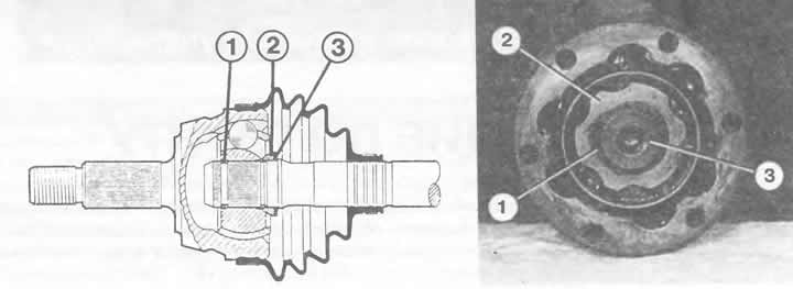
Left: Outer joint of the drive shaft:
1 - retaining ring;
2 - spacer washer;
3 - disc spring.
Right: internal homokinetic hinge (2):
1 - lock washer;
3 — drive shaft.
Removal the outer hinge. All models
Remove the drive shaft.
If the cuff is in order, you should bend back the large clamp and move the protective cuff back.
If the cuff is damaged, it should be removed completely.
Hit the hinge from the inside with a strong blow using an aluminum or plastic hammer to move the hinge off the shaft.
Before installing the new joint, insert a new retaining ring into the groove of the drive shaft.
Install the disc spring and spacer washer, if they were installed in the corresponding drive shaft version, as shown in the figure above. Don't forget the rubber seals!
When installing, push the joint onto the shaft using a plastic hammer until the retaining ring is secured.
Lubricate the joint: for a new joint with an external diameter of 80 or 90 mm, 90 g of MoS₂ grease (VW G 6) is required, 40 g in the joint and 50 g in the cuff.
Hinges with an outer diameter of 98 mm require more grease: 120 g of MoS₂ grease (VW G 6), with 80 g in the joint and 40 g in the cuff.
If used joints are being installed, all that is required is to add grease.
Squeeze the cuff clamps tightly.
Removal the internal hinge. Homokinetic hinge
Remove the drive shaft.
Using two narrow screwdrivers, remove the retaining ring that holds the joint on the drive shaft from the groove on the end of the shaft and remove it.
Now pull the joint off the shaft; if necessary, help yourself with a plastic or aluminum hammer.
If the joint cannot be removed from the shaft, it will have to be pressed out using a repair press in the workshop.
When installing, put the cuff on first.
If your car has a hinge with a disc spring, then before installation you need to put the spring on the shaft or check its position: along the outer edge it should be with the convexity towards the hinge.
Place the joint on the axle shaft and install the retaining ring.
To get the snap ring into the groove, clamp the axle shaft in a vice, place a large socket head or piece of pipe over the inside of the joint, and hit it sharply with a hammer. The joint will move back slightly, bending the spring, and the snap ring will fit into the groove.
Lubricate the joint: for a new joint with an outer diameter of 100 mm, 90 g of MoS₂ grease (VWG 6) is required, 40 g in the joint and 50 g in the cuff.
Hinges with an outer diameter of 108 mm require more grease: 120 g of MoS₂ grease (VW G 6), with 35 g in the joint and 85 g in the cuff.
For used cardan joints, you only need to add grease.
Before screwing the hinge (or flange cuff) apply VW D 3 sealing agent to the sealing surface between the cuff flange and the joint.
Removal the inner joint. "Tripod" joint
Tripod joints cannot be separated from the drive shaft. As spare parts, they are supplied complete with a half shaft and a protective cuff. Therefore, when replacing, it is necessary to remove the outer joint and replace the shaft with the inner joint.
If only the protective sleeve of the Tripod joint is defective, then the outer joint must first be removed. The sleeve can be moved along the cleaned drive shaft to the Tripod joint. Critical point: the sleeve must be lifted above the protrusion in the middle of the shaft. To do this, lubricate the protrusion with consistent grease and lift the sleeve above the thickening with a blunt round tool (with a spoon handle).
The joint contains 140 g of consistent grease G 000 605. When replacing the cuff, only a small amount of grease needs to be added.
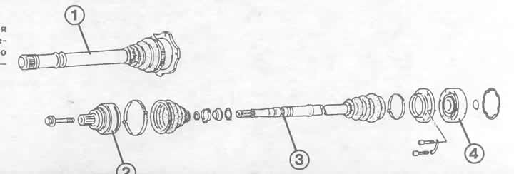
The tripod cardan joint (1) cannot be separated from the drive axle. Homokinetic joints, on the contrary, can be removed from the drive shaft itself (3) - both the outer (2) and the inner (4).