
Table of contents: Removal the front disc brake caliper ↓ Replacing brake piston seals ↓ Replacing the front brake disc ↓
In principle, both pads on the right or left must be replaced. Only pads with "General approval for operation" (in German "Allgemeine Betriebserlaubnis" — ABE). Since the pistons in the brake calipers extend further and further with increasing wear of the pads, they must be put back in place before installing new, thicker pads.
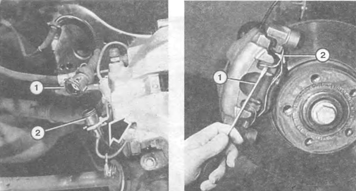
Removal the front brake pads, step one.
Left: Disconnect the brake pad wear indicator plug (1) by pressing the wire pin down. Remove the second component of the plug (2) from the holder at the disc brake caliper. To do this, carefully lift the plastic latch (arrow) with a screwdriver, turn the plug and remove it from the holder.
Right: Using a screwdriver (1), release the spring clip (2) on the disc brake caliper.
In this case, the brake fluid is squeezed out through the pipeline into the receiver. If an excessive amount of unnecessary fluid was added in the past, this excess must now be pumped out. Otherwise, the protruding brake fluid will spill onto the metal parts located in the engine compartment. For pumping out, use only a completely clean pipette or an old medical syringe - do not suck out with your mouth under any circumstances!
Raise the car from the front and secure it.
Remove the wheel.
Turn the steering wheel to allow easy access to the pads.
Disconnect the brake pad wear indicator plug by pressing the cotter pin downwards.
Disconnect the other half of the plug element from the holder. To do this, carefully lift the plastic latch with a screwdriver, turn the plug and remove it from the holder.
Use a screwdriver to detach the spring latch on the outside of the disc brake caliper.
Remove the cap on the inside of the brake caliper.
Insert the socket wrench into the now exposed internal hex of the bolt and loosen both bolts (illustration bottom left).
Pull out the bolts and remove the disc brake caliper bracket.
Hang the removed bracket on a wire to the shock absorber strut.
Remove the pads on the right and left from the disc brake caliper brackets: the inner pad is removed with the mounting brackets from the brake cylinder piston, the outer pad - possibly with the application of force - is removed at the point where it is glued to the caliper.
Remove any remaining adhesive film from the surface where the outer lining is adjacent.
Clean the brake caliper; first of all, the guide rails must not show any signs of rust.
Install new pads; to glue the outer support, remove the protective film in the gluing areas.
Replace the caliper.
Tighten the guide bolt to 25 Nm and put the cap back on.
After assembly, press the brake pedal several times until the pads are pressed against the brake discs. Otherwise, there will be no braking effect!
When driving the first 500 km with new brake pads, brake as carefully as possible.
Removal the front disc brake caliper
Each of the front disc brake calipers is secured to the shock absorber strut with two so-called serrated bolts. These bolts have a serrated surface behind the hex head, preventing accidental loosening or loss of the bolt. These serrated bolts should never be replaced with regular bolts!
Remove the wheel
Remove the brake pads with the brake caliper brackets (as described in the previous section).
Hang the brake caliper with the hose connected so that the hose is not stretched.
Or remove the brake hose or tube. In this case, press the brake pedal and hold it to prevent the brake fluid from leaking out.
Loosen the caliper mounting bolts on the brake shield.
Before installation, clean the ribbed surfaces of the ribbed bolts.
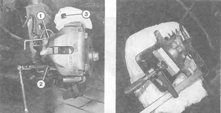
Left: Loosen both Allen bolts located in the protective shells (1 and 2) after removing the protective cap (3).
Right: This shows how a C-clamp is used to push back the plunger in the disc brake caliper so that new brake pads can be installed. Use a small piece of wood to protect the piston.
Tighten the knurled bolts to 125 Nm.
Reinstall the brake hose or pipe.
Bleed air from the brake system if the brake line or hose has been removed.
Before starting to move, press the brake pedal several times until the normal pedal travel is established.
Replacing brake piston seals
If the brake piston seal in the disc brake caliper has been damaged, you need to replace it as soon as possible, otherwise the brake piston will soon start to seize due to dirt and corrosion. The seal can only be purchased complete with a brake piston sealing ring. To install both parts, you need to remove the piston from the brake cylinder body. For safety reasons, it is better to entrust this work to a workshop. For example, remove the disc brake caliper and take it to a workshop.
Replacing the front brake disc
Brake discs must be replaced on both sides at the same time. Replacing one side will result in uneven braking action.
Disconnect the disc brake caliper and secure it to the body with wire; hydraulic hoses remain connected.
Now you can remove the brake disc from the wheel hub by hand.
Disconnect the disc brake caliper and secure it to the body with wire; hydraulic hoses remain connected.
If it is rusted, help with sharp blows of a hammer, but only if this disk needs to be changed anyway