
Table of contents: TO No.29 ↓ Removal the brake drum ↓ Checking the condition of the brake… ↓ Removal brake pads ↓ Removal the drum brake cylinder ↓
TO No.29
Press the brake pedal with your hand.
Free travel should be a maximum of ⅓ of the total pedal travel.
A longer pedal free play indicates that the brake pads have worn down to their minimum thickness and need to be replaced.
Or the parking brake is not adjusted correctly.
Excessively long pedal travel can also be caused by jammed brake pads or a rusted brake caliper.
There may be air in the brake system.
Removal the brake drum
Remove one wheel bolt.
The brake drum can be removed without removing the wheel. In this case:
Raise the car from behind.
Turn the wheel disc or brake drum so that the hole for the bolt is at the front and top in the direction of the vehicle.
Using a screwdriver, press the adjusting wedge upwards through the bolt hole - this will press the brake pads.
Remove the crown cap of the wheel (see fig. in chapter "Wheels and tires").
Bend and remove the safety pin in the wheel hub bearing.
Remove the crown retainer, unscrew the hex nut, remove the thrust washer and the outer wheel bearing.
Remove the brake drum.
When installing, be sure to adjust the wheel hub bearing play (see chapter "Wheel suspension and steering").
Bring the shoes to the brake drum by pressing the brake pedal hard once.
Tip: If you have an older car and the rusted adjusting wedge cannot be pushed up, have an assistant press the brake pedal while you push the wedge up. Then release the brake pedal and only then remove the screwdriver from the hole, otherwise the wedge will go down again. Make sure that you only press the pedal when both brake drums are installed.
Checking the condition of the brake drums
The friction surface in the drum should be as smooth as possible.
If deep grooves or scratches are visible (due to brake pads worn down to the rivets), the drum can be bored.
The inner diameter of the new brake drums is 230 mm.
After boring, the internal diameter should not be more than 231 mm, otherwise both brake drums must be replaced.
Removal brake pads
Remove the brake drum.
Press the spring plate of the brake shoe holder with pliers, turn it 90° (holding the mounting pin at the back of the shield,
so that it does not rotate together with the shield) and remove them, then remove the springs.
Detach the return spring of the adjusting wedge.
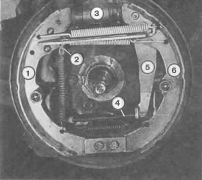
With the brake drum removed, we see the following elements in the rear wheel brake mechanism:
1 - front brake shoe;
2 - adjusting wedge;
3 - wheel brake cylinder;
4 — parking brake cable drive;
5 — parking brake lever;
6 - rear brake shoe.
Separate the brake shoe from the lower support and the brake cylinder piston.
Disconnect the parking brake cable from the removed brake shoes.
Remove the return springs at the top and bottom.
Pull the adjusting wedge out of the push rod.
Unhook the main spring from the top of the pressure rod. If necessary, secure the pressure rod in a vice.
When assembling, secure the pressure bar in a vice.
Attach the main spring to the pressure rod and brake shoe. How to install the spring is shown in the picture above on this and the next page.
Install the brake shoe on the pressure rod, insert the adjusting wedge from above. Its projection is directed towards the brake shoe.
Install the brake lever of the passive shoe into the protrusion of the pressure rod, attach the upper return spring.
With the brake shoes still loose, attach the parking brake cable to the parking brake lever.
Removal the drum brake cylinder
Remove the brake drum.
Remove the brake pads.
Unscrew the bleed valve.
Disconnect the brake hose. If you are not going to install a new brake cylinder right away, you should depress the brake pedal and leave it in this position to prevent unnecessary loss of brake fluid.
Remove the two mounting bolts from the rear of the drum brake shield and remove the brake cylinder.
[The original version of the article is posted on the website «AUDIMANUAL.ru»]