Repair Chevrolet Repair Toyota Repair Honda Repair AvtoVAZ Repair Mercedes-Benz Repair BMW Repair Opel
Home  |  Contacts  |  Sitemap  |    
English Русский
Български
Беларускі
Український
Српски
Hrvatski
Română
Polski
Slovenský
Magyar
AudiManual.ru


  • AUDI 80
  • AUDI 100
  • AUDI A3
  • AUDI A4
  • AUDI A6
  • AUDI A8
  • AUDI Q
  • OTHER
  • ARTICLES
B8 (2007-2015) B7 (2004-2008) B6 (2000-2006) B6 (2000-2006, petrol) B5 (1994-2001) B5 (1994-2001, petrol)

ABS System Components — Removal and Installation (Audi A4 B5)

  • Home
  • Audi A4
  • B5 (1994-2001)
  • Chassis
  • Brake system
  • ABS System Components — Removal and Installation
            0
Table of contents: Hydraulic block ↓ Electronic control unit Bosch ABS 5.0 ↓ Front wheel sensor ↓ Rear wheel sensor ↓

Hydraulic block


Warning: On ABS models, disconnect the battery before opening the hydraulic system and do not reconnect the battery until the system has been bled. Failure to do so may cause air to enter the hydraulic pump, where it will be extremely difficult to remove, requiring specialized diagnostic equipment (see paragraph 2).


Note: Audi states that after removal and installation of the units, the system operation must be checked using specialized equipment. Taking this into account, it is recommended to entrust the removal and installation of the units to specialists of the dealer car service. If you decide to carry out these operations yourself, check the system on diagnostic equipment at the earliest opportunity.


Removal


1. Disconnect the negative cable from the battery.

2. If necessary, unscrew the fastening screw and remove the plastic relay cover from the hydraulic unit of the regulator.

3. Release the latch and disconnect the wiring connector from the hydraulic unit.

4. If necessary, unscrew the nut and disconnect the ground wire from the regulator.

5. Raise the front of the vehicle and install safety stands. Remove the left front wheel.

6. Attach a section of hose to the left caliper fitting, lowering the other end into the jar, as described in paragraph 2. Open the nipple and press the brake pedal all the way down and secure it there with a wooden block, resting it against the seat. After finishing removing the fluid, tighten the nipple.


Note: The brake pedal must be kept depressed until the hydraulic pipes are fully connected to the hydraulic unit, until the very end of the procedure.


7. Wipe the area around the tube connections. Remember how the tubes are connected to the unit so that they can be installed correctly during assembly. Unscrew the connection nuts and carefully remove the tubes. Isolate the tubes from dirt getting into the system. Immediately wash away any spilled liquid.

8. Loosen the hydraulic unit mounting nuts and remove the unit from the engine compartment. If necessary, the mounting bracket can be removed by unscrewing the mounting bolts. Damaged or worn regulator supports must be replaced.

Note: When removing and storing, keep the unit upright to prevent liquid from spilling out and air from entering.


Installation


Note: New units are supplied as spare parts fully bled and filled with brake fluid. It is vital to keep the plugs closed until the tubes are connected to prevent air from getting inside.


9. Install the block on the bracket and tighten the mounting nuts to the specified torque.

10. Remove the plugs and connect the hydraulic pipes to their places. Tighten the union nuts to the specified torque.

11. Connect the wiring connector to the hydraulic unit and, if equipped, install the cover.

12. Fill the reserve tank with fresh brake fluid (see Weekly Checks) and connect the battery.

13. Remove the brake pedal stop and bleed the entire hydraulic system as described in paragraph 2. Check the brakes before driving on the road. Contact your dealer to have the ABS system checked as soon as possible.


Electronic control unit Bosch ABS 5.0


Removal


14. Remove the rear seat cushion as described in chapter 11 to gain access to the BEU.

15. Loosen the mounting screws and remove the unit.

16. Turn off the ignition, release the latch and disconnect the wiring connector from the unit. Remove the unit from the car.

Installation


17. Installation - reverse procedure.

Front wheel sensor


Removal


18. Disconnect the ground wire from the battery.

19. Apply the handbrake. Place chocks under the rear wheels. Raise the front of the car and install safety stands. Remove the wheel in question.

20. Follow the wiring from the sensor, free it from all fasteners and remember the layout. Disconnect the wiring connector.

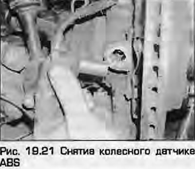
21. Carefully pull the sensor out of the steering knuckle bracket and remove it from the vehicle. Once the sensor is removed, remove the rubber seal and retaining sleeve from the bracket (fig. 19.21).

21. Carefully pull the sensor out of the steering knuckle bracket and remove it from the vehicle.…


Installation


22. Make sure the sensor and its mounting surface in the steering knuckle are clean and apply a small amount of fine copper based grease.

23. Insert the bushing into the rack until it stops, then insert the sensor with the rubber seal. Correctly lay and secure the wiring and push the sensor until it stops.


24. Connect the wiring connector.

25. Install the wheel (if you filmed) and lower the vehicle. Tighten the wheel bolts to the specified torque as described in Chapter 1A or 1B. Connect the battery.

Rear wheel sensor


Removal


26. Disconnect the ground wire from the battery.

27. Remove the rear seat cushion as described in chapter 11 and locate the sensor wiring connector. Disconnect the connector and release the wiring from the fasteners.

28. Place chocks under the front wheels, engage reverse (or "P" in the case of an automatic transmission) gear. Raise the rear of the car and install safety supports. Remove the corresponding wheel.

29. Follow the wiring from the sensor to the connector and release the sensor wiring from the common braid. Unscrew the mounting bolts and remove the protective cover of the wiring from the rear beam, release the rubber seal in the body opening and pull the wiring so that it can be removed together with the sensor.

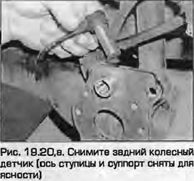
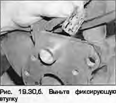
30. Carefully pull the sensor out of the rear beam and remove it from the car. After removing the sensor, remove the bushing (fig. 19.30, a, b).

30. Carefully pull the sensor out of the rear beam and remove it from the car. After removing the…

Installation


31. Make sure the mating surfaces of the lever and sensor are clean. Lubricate the locking sleeve and sensor with fine copper grease.


32. Insert the bushing into the hole in the rear beam, then insert the sensor. Put the sensor wiring in place and insert the sensor until it stops.

33. Make sure the wiring is routed correctly and secure it with all fasteners. Install the protective cover on the rear beam, tightening the fastening screws securely. Push the wiring into the body opening and install the rubber seal.

34. Install the rear wheel, lower the vehicle. Tighten the wheel mounting bolts to the specified torque as described in Chapter 1A or 1B.

35. Connect the sensor wiring connector, install the rear seat cushion and connect the battery.

[The original article is available on the website AUDIMANUAL.ru]
The article was checked by auto expert Timur Bazhenov
This article is available at russian, bulgarian, belarusian, ukrainian, serbian, croatian, romanian, polish, slovak, hungarian

Share information:
Previous articles
Audi A4 B5: Brake system
Next articles

Anti-lock braking system ABS — general information
Brake light contact sensor — removal, installation and adjustment
Handbrake cables — removal and installation
Handbrake lever — removal and installation
Vacuum pump (diesel engines) — removal and installation


Similar articles on other Audi car models:
Fuel injection system parts — removal and installation Audi 80 B3 (1986-1991, petrol)
Throttle Cable and Throttle Pedal Components — Removal and… Audi 100 C3 (1982-1990, diesel)
Removal and installation of the exhaust system Audi A3 Type 8L (1996-2003)
Removal and installation of cylinder head of petrol engines V6… Audi A6 C5 (1997-2004)
Removal and installation of the exhaust system Audi A8 D2 (1994-2002)
Removal and installation of sensors and some lines of the engine… Audi Q7 Typ 4L (2005-2015, diesel)
Removal and installation the cooling system pump Audi A2 (1999-2005)
Link to this page in different formats


Visitor comments

No comments yet


How much will 37 + 24 =


A4(B8, 2007-2015) 
  • General information
  • Operating instructions
  • Power unit
  • Petrol engines 1.8 l
  • Petrol engines 1.8/2.0 l
  • Petrol engines 3.0 l
  • Petrol engines 3.2 l
  • Fuel system (petrol)
  • Diesel engines 2.0 l (CA*)
  • Diesel engines 2.0 l (CJCB)
  • Diesel engines 2.7/3.0 l
  • Diesel engines 3.0 l
  • Fuel system (diesel)
  • Transmission
  • Manual gearbox 0B1
  • Manual gearbox 0B2
  • Manual gearbox 0B3
  • Manual gearbox 0B4
  • Automatic transmission 0B5
  • Automatic transmission 0B6
  • Automatic transmission 0AW
  • All-wheel drive system
  • Chassis
  • Front suspension
  • Rear suspension
  • Brake system
  • Steering system
  • Body
  • Exterior
  • Interior
  • Seats
  • Doors, locks and windows
  • Security system
  • Heating and air conditioning
  • Electrical equipment
  • Audio system
  • Power devices
  • Equipment and devices
  • Lighting and lamps
  • Electrical circuits
 
A4(B7, 2004-2008) 
  • General information
  • Introduction to manual
  • Troubleshooting
  • Operating instructions
  • Maintenance
  • Power unit
  • Petrol engines 2.0 (ALT)
  • Petrol engines 2.0 (TFSI)
  • Petrol engines 1.8 (MPI)
  • Diesel engines
  • Cooling system
  • Air conditioner
  • Fuel and exhaust system
  • Ignition system
  • Starting and charging
  • Transmission
  • Clutch
  • Manual gearbox
  • Automatic gearbox
  • Drive shafts
  • Chassis
  • Brake system
  • Front suspension
  • Rear suspension
  • Steering
  • Body
  • Exterior
  • Interior
  • Electrical equipment
  • Equipment and devices
  • Lighting and signaling
  • Windscreen wipers and washers
  • Electrical diagrams
  • Electrical diagrams (since 2007)
 
A4(B6, 2000-2006) 
  • General information
  • Vehicle Description
  • User manual
  • Maintenance
  • Power unit
  • Gasoline engine
  • Diesel engine
  • Lubrication system
  • Cooling system
  • Supply system
  • Injection system
  • Exhaust system
  • Ignition and control
  • Transmission
  • Gear box
  • Clutch and drive shafts
  • Chassis
  • Brake system
  • Car suspension
  • Steering
  • Body
  • Heating and ventilation
  • Exterior (external elements)
  • Interior (internal elements)
  • Electrical equipment
  • Power devices
  • Lighting and appliances
  • Electrical circuits
 
A4(B6, 2000-2006, petrol) 
  • General information
  • Introduction to the guide
  • Car care
  • Power unit
  • Engine repair
  • Lubrication system
  • Cooling system
  • Injection and control system
  • Ignition system
  • Power and exhaust system
  • Transmission
  • Clutch and drive shafts
  • Car gearbox
  • Chassis
  • Suspension and wheels
  • Steering
  • Brake system
  • Body
  • Interior
  • Exterior
  • Electrical equipment
  • Equipment and devices
  • Lighting and signaling
  • Power devices
  • Electrical circuits
 
A4(B5, 1994-2001) 
  • General information
  • Introduction to the guide
  • Car care
  • Maintenance (gasoline)
  • Maintenance (diesel)
  • Power unit
  • Gasoline engines
  • Diesel engines
  • Engine overhaul
  • Cooling system
  • Fuel injection (gasoline)
  • Fuel system (diesel)
  • Exhaust system
  • Ignition system
  • Transmission
  • Clutch
  • Mechanical gearbox
  • Automatic gearbox
  • Drive shafts
  • Chassis
  • Brake system
  • Car suspension
  • Steering
  • Body
  • Exterior
  • Interior
  • Doors, locks and windows
  • Heating and ventilation
  • Electrical equipment
  • Power devices
  • Equipment and devices
  • Electrical circuits
 
A4(B5, 1994-2001, petrol) 
  • General information
  • Vehicle description
  • Maintenance
  • Power unit
  • Engine repair
  • Turbocharging
  • Exhaust system
  • Cooling system
  • Ignition system
  • Fuel system
  • Motronic injection system
  • MPI and MPFI injection system
  • Transmission
  • Clutch
  • Gearbox and shafts
  • Chassis
  • Steering
  • Car suspension
  • Brake system
  • Wheels and tires
  • Body
  • Heating and ventilation
  • Body parts
  • Electrical equipment
  • Fuses and relays
  • Power devices
  • Lighting and lamps
  • Tools and devices
  • Electrical circuits
 
AudiManual.ru © 2017-2026 · Mobile version · Feedback · Sitemap: EN BG BY UA RS HR RO PL SK HU · Site search · News and articles
80 B2 · 80 B3 petrol · 80 B3 · 80 B4 · 100 C3 diesel · 100 C3 petrol · 100 C3 · 100 C4 petrol · 100 C4 · A3 Type 8L · A4 B5 petrol · A4 B5 · A4 B6 petrol · A4 B6 · A4 B7 · A4 B8 · A6 C4 · A6 C5 · A6 C5 Allroad · A8 D2 · Q5 Type 8R · Q7 Typ 4L · Audi A2 ·
This site uses cookies 🍪. Click the button to accept this fact.