
Table of contents: Models with a composite stand and… ↓ Models with separate stand and wheel… ↓ All models ↓
1. Apply the parking brake, remove the trim from the corresponding front wheel.
2. Loosen the drive shaft nut or bolt.
3. Loosen the wheel bolts.
4. Jack up the front of the car and support it on axle stands.
5. Remove the wheel.
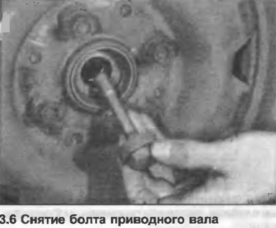
6. Remove the drive shaft nut and washer or bolt (photo).
7. Unscrew and remove the lower cover of the drive shaft (where is it used) from the gearbox.
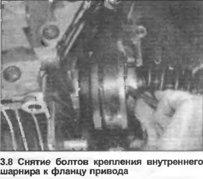
8. Under the vehicle, loosen and remove the bolts securing the inner CV joint to the transmission drive flange (photo). Note the location of the bolt plates. Support the inner end of the drive shaft, or temporarily tie it up on one side. Remove the spacer, if any.
Models with a composite stand and wheel bearing housing (to chassis F89J373598 - April 1988)
9. On models with direct action steering, mark the position of the lower ball joint arm relative to the wishbone - this is necessary for setting the wheel camber. Loosen the nuts, release the ball joint arm.
10. On models with power steering, disconnect the front stabilizer link from the stabilizer bar by unscrewing the nut. Loosen and remove the wishbone pivot bolts, and rotate the wishbone downward.
11. Using a hub puller, remove the drive shaft from the front wheel hub, then remove the drive shaft from under the vehicle.
12. If it is necessary to move the vehicle without the drive shaft, the wheel bearing, inner tracks must be clamped together with a long bolt and washers. If this is not done, the bearing may be damaged. Where equipped, also assemble the suspension parts.
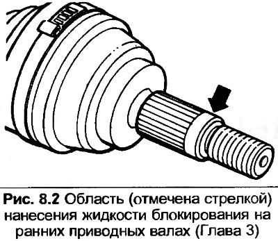
13. Clean the grooves on the outer end of the drive shaft and inside the hub. All traces of old locking fluid must be removed.
14. Squeeze 5.0 mm of locking fluid onto the outer end of the drive shaft slots (Fig. 8.2).
15. Insert the drive shaft into the hub.
16. On power steering models, align the control arm holes and install the pivot bolts. Do not fully tighten the bolts until the weight of the vehicle is on the wheels. Connect the stabilizer bar link and tighten the nut.
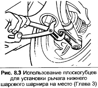
17. On direct-acting steering models, install the ball joint arm to the control arm. Using pliers, pull the arm to the pre-marked position, then tighten the nuts. Be careful not to pinch the rubber ball joint dust boot.
Models with separate stand and wheel bearing housing (chassis number F89J373599 - since April 1988)
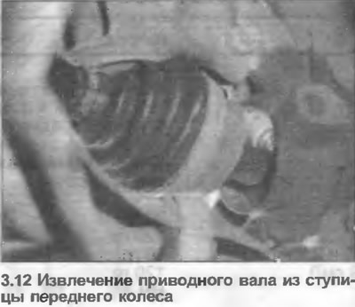
18. Turn the steering wheel to its maximum angle, remove the drive shaft from the front wheel hub and take it out from under the car (photo). On models with ABS, slightly move the speed sensor away.
19. If it is necessary to move the vehicle without the drive shaft, the wheel bearing, inner tracks must be clamped together using a long bolt and washers. If this is not done, the bearing may be damaged. Where equipped, also assemble the suspension components.
20. Clean the grooves on the outer end of the drive shaft and inside the hub.
21. With the steering at its maximum turning angle, insert the drive shaft into the hub. On ABS models, push the speed sensor all the way into its original position.
All models
22. Where fitted, after cleaning the seat, position the new gasket on the inner end of the drive shaft. The gasket may have its own adhesive, remove the foil before fitting.
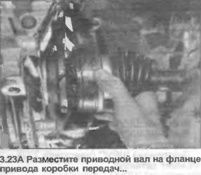
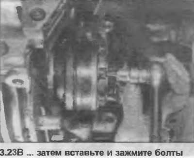
23. Place the drive shaft on the gearbox drive flange, then insert and tighten the bolts and plates to the tightening torque specified in the Specification (photo).
24. Install the lower drive shaft cover (where is it used).
25. If a drive shaft nut is used, apply thread locking fluid to the threads, install it with the washer and tighten moderately.
26. If a drive shaft bolt is used, install and moderately tighten a new bolt.
27. Install the wheel, tighten the bolts moderately.
28. Lower the car to the ground.
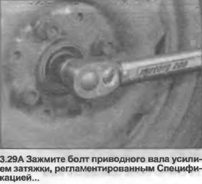
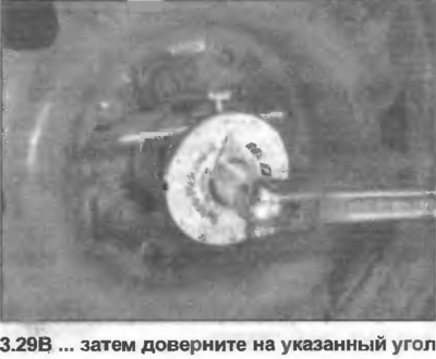
29. Fully tighten the drive shaft nut (bolt) and wheel bolts to the torque specified in the Specification. Note that the bolt is tightened to the specified torque specified in the Specification and then turned to the specified angle (photo). Where equipped, also tighten the wishbone pivot bolts. Fit the wheel cover.
30. If blocking fluid was used (in paragraph 14), allow it to become secure before operating the vehicle.