
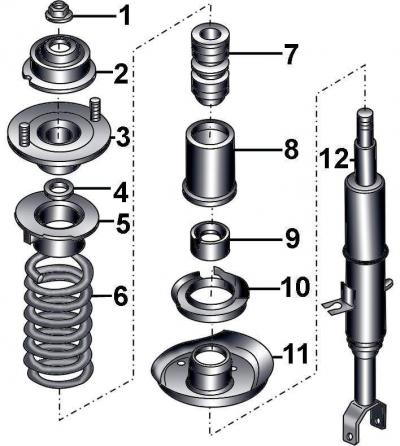
Fig. 12–5. Shock absorber strut elements: 1 – flange nut, 50 Nm; 2 – spacer sleeve; 3 – upper support of the shock absorber strut; 4 – washer; 5 – upper spring support; 6 – cylindrical spring; 7 – buffer; 8 – protective cover; 9 – protective cover; 10 – lower spring support; 11 – lower spring plate; 12 – shock absorber
Secure the shock absorber strut (Fig. 12-5) of the front suspension in a fixture secured in a vice and use the special device VAG 1752/6 to compress the spring so that it moves away from the top of the strut. When using the special device for compressing springs, the spring coils must be firmly grasped and compressed from opposite sides.
Warning: The spring has a very high compression force, so use only a very reliable tool. Do not tie the spring with wire under any circumstances.
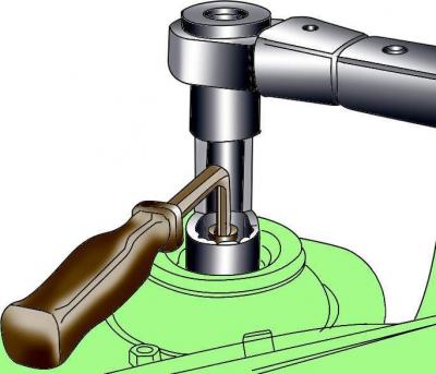
Fig. 12–6. Unscrewing the central nut securing the shock absorber rod
After securing the shock absorber rod with a wrench to prevent it from turning, use another open-end wrench or special wrench 3353 to unscrew the central nut securing the shock absorber rod (Fig. 12–6).
Remove the spacer sleeve, upper shock absorber strut support, washer and upper spring support from the shock absorber rod.
Remove the spring together with the spring compressor.
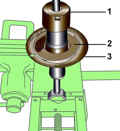
Fig. 12–7. Location of the protective cover (1), spring support (2) and lower spring plate (3) on the shock absorber strut
Remove the protective cover 1 (Fig. 12–7) and the lower spring support 2. Using a plastic hammer, knock the lower spring plate 3 upwards.
Installation
When installing, it is necessary to use springs with the same technical characteristics on one axle of the vehicle (with the same color markings).
Check the shock absorber for fluid leaks. Check the entire length of the shock absorber rod for pitting. Check the shock absorber body for mechanical damage. Set the shock absorber in a vertical position and check its operation by moving the rod to its full stroke, as well as up and down by 50-100 mm. In all cases, the shock absorber rod should move smoothly, with noticeable resistance. If the shock absorber rod moves jerkily or there is mechanical damage, the shock absorber must be replaced.
Secure the shock absorber in a vice with soft jaws.
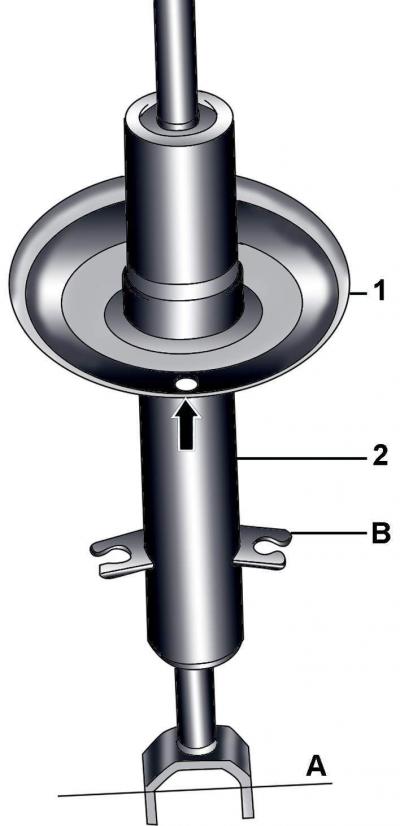
Fig. 12–8. Correct hole position when installing the lower spring plate on the shock absorber: 1 – lower spring plate; 2 – shock absorber; A – axle of the lower shock absorber fork mount; B - clamps
Install the lower spring plate on the shock absorber so that the hole in the spring plate is perpendicular to the hole in the fork of the lower shock absorber mount, while the clamps should be located on the side of the hole (Fig. 12-8). The deviation of the center of the hole in the lower spring plate from the vertical should be no more than±2°.
Install the lower spring support and protective cover.
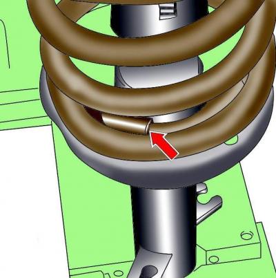
Fig. 12–9. Correct positioning of the lower spring coil in the plate
Install the coil spring so that its lower end is correctly positioned in the lower spring plate (Fig. 12–9).
Install the upper spring plate so that the axis passing through the mounting threaded posts is parallel to the axis of the lower shock absorber mount. A deviation of no more than±2° is allowed.
While holding the shock absorber rod from turning, screw on a new shock absorber rod flange nut and tighten it to a torque of 50 N·m (see Fig. 12–6).
Carefully remove the spring compressor.
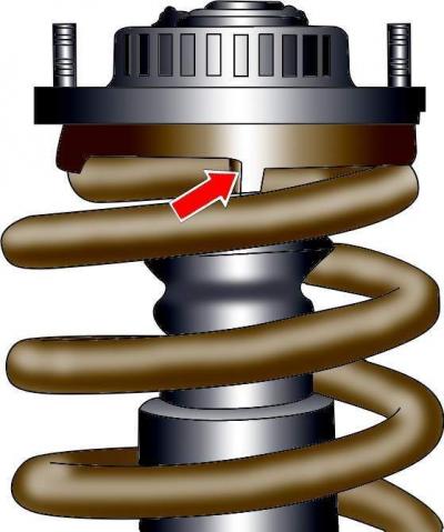
Fig. 12–10. Correct positioning of the upper spring coil on the shock absorber strut
Check that the top coil of the spring is correctly positioned on the top spring plate (Fig. 12–10).
Install the shock absorber strut on the vehicle.
[The original article is located on the online resource audimanual.ru]