
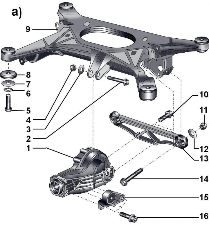
Fig. 12–17a. Rear suspension design elements:
a: 1 – main reverse gear; 2 – bolt, 40 Nm; 3 – washer; 4 – self-locking nut, 40 Nm; 5 – bolt, 150 Nm + turn further by 90°; 6 – blocking washer; 7 – washer; 8 - washer; 9 – rear lower frame; 10 – cylindrical head bolt; 11 – self-locking nut, 40 Nm; 12 – washer; 13 –– rear cross beam; 14 – combination bolt; 15 – front support of the main rear gear; 16 – cylindrical head bolt;
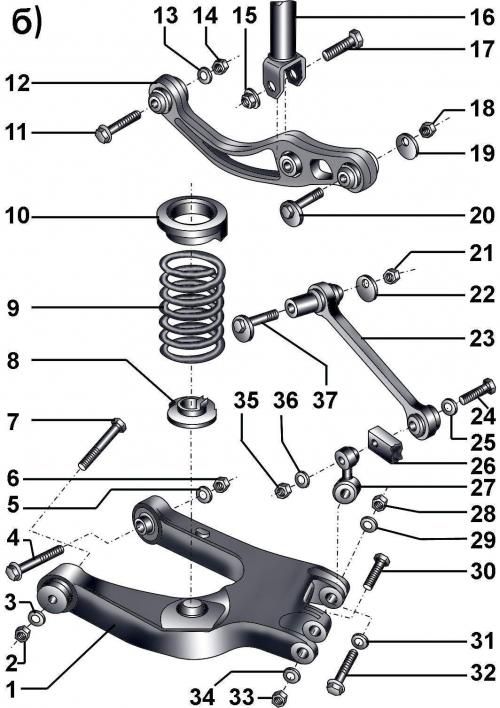
Fig. 12–17b. Elements of the rear suspension design:
b: 1 – lower trapezoidal lever; 2 – self-locking nut, 80 Nm + turn further by 90°; 3 – washer; 4 – combination bolt; 5 – washer; 6 – self-locking nut, 80 Nm + turn further by 90°; 7 – combination bolt; 8 – lower spring support; 9 – cylindrical spring; 10 – upper spring support; 11 – combination bolt; 12 – transverse lever; 13 – washer; 14 – self-locking nut, 80 Nm + turn further by 90°; 15 – self-locking nut, 65 Nm; 16 – shock absorber; 17 – combination bolt; 18 – self-locking nut, 95 Nm; 19 – eccentric washer; 20 – eccentric bolt; 21 – self-locking nut, 70 Nm + turn further by 90°; 22 – eccentric washer; 23 – control lever; 24 – bolt; 25 – washer; 26 – rear steering knuckle; 27 – earring; 28 – self-locking nut, 80 Nm + turn further by 90°; 29 – washer; 30 – flange bolt; 31 – washer; 32 – bolt; 33 – self-locking nut, 80 Nm + turn further by 90°; 34 – washer; 35 – self-locking nut, 70 Nm + turn further by 90°; 36 – washer; 37 – eccentric bolt;
b: 1 – lower trapezoidal lever; 2 – self-locking nut, 80 Nm + turn further by 90°; 3 – washer; 4 – combination bolt; 5 – washer; 6 – self-locking nut, 80 Nm + turn further by 90°; 7 – combination bolt; 8 – lower spring support; 9 – cylindrical spring; 10 – upper spring support; 11 – combination bolt; 12 – transverse lever; 13 – washer; 14 – self-locking nut, 80 Nm + turn further by 90°; 15 – self-locking nut, 65 Nm; 16 – shock absorber; 17 – combination bolt; 18 – self-locking nut, 95 Nm; 19 – eccentric washer; 20 – eccentric bolt; 21 – self-locking nut, 70 Nm + turn further by 90°; 22 – eccentric washer; 23 – control lever; 24 – bolt; 25 – washer; 26 – rear steering knuckle; 27 – earring; 28 – self-locking nut, 80 Nm + turn further by 90°; 29 – washer; 30 – flange bolt; 31 – washer; 32 – bolt; 33 – self-locking nut, 80 Nm + turn further by 90°; 34 – washer; 35 – self-locking nut, 70 Nm + turn further by 90°; 36 – washer; 37 – eccentric bolt;
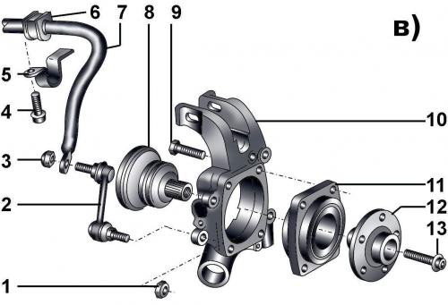
Fig. 12–17c. Elements of the rear suspension design:
v: 1 – self-locking nut, 45 Nm; 2 – anti-roll bar earring; 3 – self-locking nut, 45 Nm; 4 – cylindrical head bolt, 30 Nm; 5 – bracket, 6 – rubber bushing; 7 – anti-roll bar; 8 – rear drive shaft; 9 – bolt, 80 Nm + turn further by 90°; 10 – rear steering knuckle; 11 – wheel bearing; 12 – wheel hub; 13 – flange bolt, 190 Nm + turn further by 180°
v: 1 – self-locking nut, 45 Nm; 2 – anti-roll bar earring; 3 – self-locking nut, 45 Nm; 4 – cylindrical head bolt, 30 Nm; 5 – bracket, 6 – rubber bushing; 7 – anti-roll bar; 8 – rear drive shaft; 9 – bolt, 80 Nm + turn further by 90°; 10 – rear steering knuckle; 11 – wheel bearing; 12 – wheel hub; 13 – flange bolt, 190 Nm + turn further by 180°
Fig. 12–17a, 12–17b, 12–17c show the elements of the rear suspension design.
Warnings: It is strictly forbidden to carry out welding and straightening work on the front suspension elements. Be sure to replace the self-locking nuts, as well as bolts with traces of corrosion.
Do not lift the vehicle by the lower rear frame.
New bolts, nuts and washers must be used during installation.