
Table of contents: Removal ↓ Installation ↓
Removal
The lower rear frame is removed together with the main rear gear, steering knuckle and rear suspension arms.
Using a screwdriver blade as a lever, remove the cap from the center of the wheel rim.
With the vehicle standing on its wheels, loosen the flange bolts securing the drive shafts to the rear wheel hubs.
Raise the rear of the car and secure it on stands. Remove the rear wheels.
Remove the rear section of the exhaust pipes.
Remove the rear muffler heat shield.
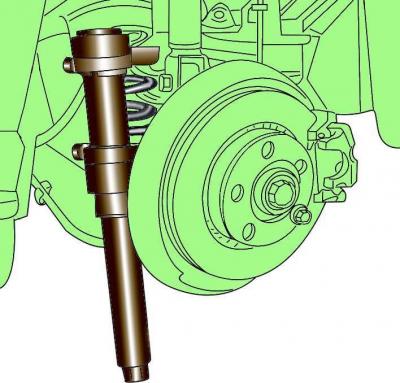
Fig. 12–18. Using the special tool VAG 1752/1 to compress the rear suspension springs
Using the special VAG 1752/1 spring compression tool, alternately compress the rear suspension springs and remove them (see Fig. 12–18). The spring coils must be securely grasped with the tool, and the spring must be compressed from opposite sides.
Warning: The spring has a high compression force, so use only a very strong tool.
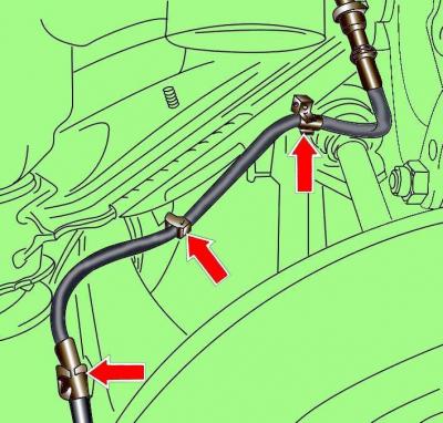
Fig. 12–24. ABS sensor wire clamp locations
Release from the clamps and move to the side the ABS sensor wires (Fig. 12–24).
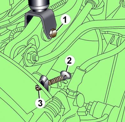
Fig. 12–25. Location of the bolt (1) securing the shock absorber to the wishbone and fastening the casing (2) of the parking brake cable (3) to the bracket and caliper
Disconnect the parking brake cable 3 from the rear wheel caliper (Fig. 12–25).
Remove the parking brake cable housing 2 from the bracket by forcefully moving the cable away from the caliper.
Unscrew bolt 1 securing the shock absorber to the wishbone.
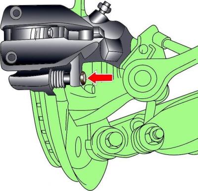
Fig. 12–26. Bolt location (the second bolt is not visible) rear brake caliper mounts
Unscrew the rear caliper mounting bolts (Fig. 12–26). Tie the caliper to the body with soft wire. The caliper should not hang on the brake hose.
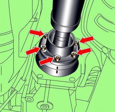
Fig. 12–27. Location of alignment marks and bolts for fastening the propeller shaft to the flange of the main rear gear
Check if there are alignment marks on the propeller shaft flange and the main reverse gear flange (Fig. 12–27). If there are no marks, apply them.
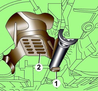
Fig. 12–28. Using a wooden wedge (1) to push the driveshaft up against the heat shield (2)
Use a wooden wedge to push the cardan shaft upwards towards the heat shield (Fig. 12–28).
Unscrew the bolts and remove the heat shield located above the propeller shaft.
Unscrew the bolts securing the propeller shaft flange to the main rear gear flange.
Free parking brake cables from the holders and, moving them towards the rear of the vehicle, remove them from the guides.
Remove the bolt and separate the parking brake cable guide.
Place a jack with the VAG 1359/2 device under the final drive and raise the jack so that the weight of the rear lower frame with the final drive is supported by the jack.
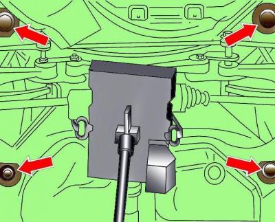
Fig. 12–29. Location of lower rear frame mounting bolts.
Unscrew the lower rear frame mounting bolts (Fig. 12–29), lower the jack and remove the lower frame with the main rear gear.
Installation
Installation is carried out in the reverse order of removal, taking into account the following.
When installing the lower frame, make sure that the fuel tank ventilation hoses are not pinched.
Screw in and tighten the new lower frame mounting bolts to a torque of 150 Nm and then turn them through an angle of 90°.
Install in place and secure parking brake cables.
Install a heat shield over the driveshaft.
In the flange of the main rear gear, clean the threads for the crankshaft mounting bolts.
When installing the propeller shaft, to avoid imbalance, align the marks on the propeller shaft flange with the marks on the main rear gear flange (see Fig. 12–27).
Check that the exhaust system components are free and do not touch the body.