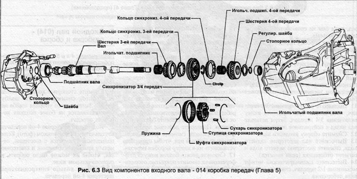
Note: 4- and 5-speed transmissions have many very similar components. Minor differences are not covered in this procedure.
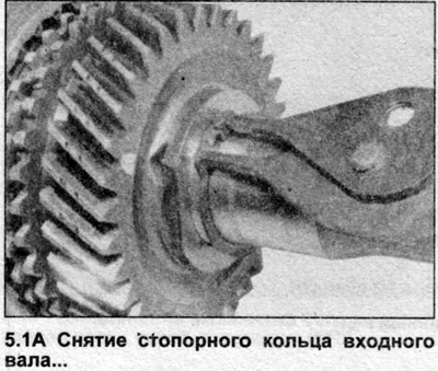
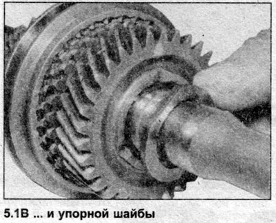
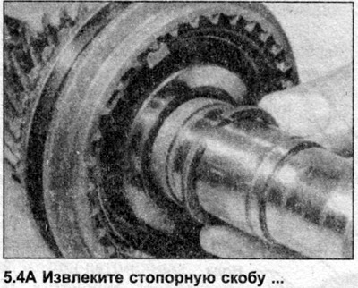
1. Remove the retaining ring from the end of the shaft (photo), remove the thrust washer (photo). Note that the thrust washer is not installed on later gearboxes.
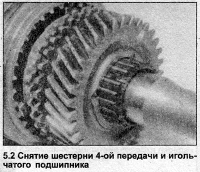
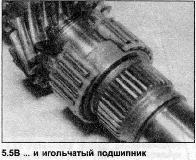
2. Lift the 4th gear pinion with the needle bearing (photo). If the bearing is removed from the pinion, mark the bearing and pinion with paint so that they can be reassembled in their original form.
3. Remove the 4th gear synchronizer ring.
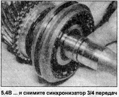
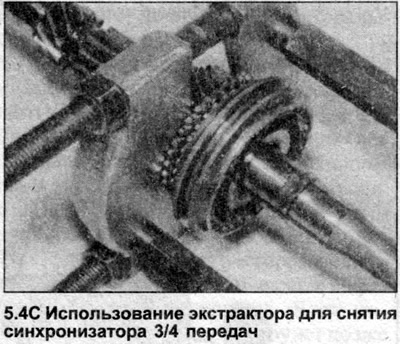
4. Remove the retaining ring securing the synchronizer hub, remove the hub from the shaft (photo).
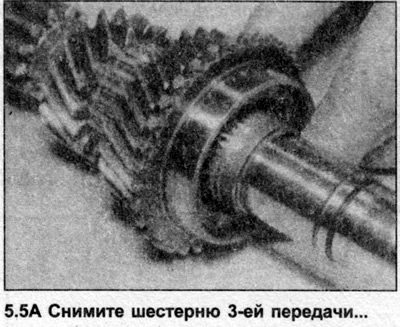
5. Remove the 3rd gear synchronizer ring, 3rd gear gear and needle bearing (photo).
6. Mark the gear and bearing so that they can be assembled correctly.
7. Before assembly, make sure all parts are clean and inspect their condition. Gearbox components are very expensive, if any gears or shafts need to be replaced, it may be more cost effective to install another gearbox.
8. Lubricate the 3rd gear needle bearing and install it on the shaft.
9. Install the 3rd gear.
10. If the synchronizer has been disassembled, look for marks on the outer edge. If there are any, the hub should be inserted according to these marks. Later models do not have marks and are not reinstalled.
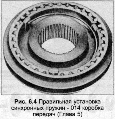
11. Install three locking crackers into the hub before installing the bushing, secure the crackers with springs, the location of the springs is shown in Fig. 6.4, the springs are installed with the angled end in the hole of the locking cracker.
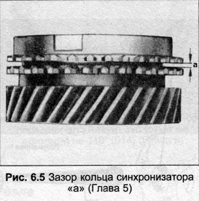
12. Install the 3rd gear synchronizer ring on the pinion cone, measure the gap (a) with a feeler gauge (Fig. 6.5). This gap must not exceed the value given in the Specifications, otherwise a new synchronizer ring must be installed.
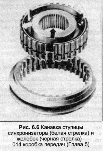
13. Note that the slots in the synchronizer hub bore are grooved at one end. The hub also has an additional groove at one end (Fig. 6.6) and these surfaces should face the 4th gear pinion.
14. Place the synchronizer on the shaft, turning the 3rd gear synchronizer ring so that the grooves on it are aligned with the synchronizer locking crackers.
15. Insert the locking ring on top of the synchronizer hub, press the synchronizer back against the locking ring. This increases the gap between the synchronizer and the 3rd gear, which ensures better lubrication of the bearing.
16. Install the 4th gear synchronizer ring, aligning the grooves in it with the synchronizer locking crackers, check the play as described in point 12.
17. Install the 4th gear and bearing, lubricate them with oil, install the thrust washer (early models) and finally the retaining ring.
18. On early models, measure the axial clearance between the 4th gear and the thrust washer. It should be at least 0.10 mm but less than 0.40 mm. If the clearance exceeds the upper limit, install a thicker thrust washer, there are three thicknesses of washers: 3.47 mm, 3.57 mm and 3.67 mm.