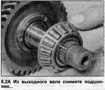
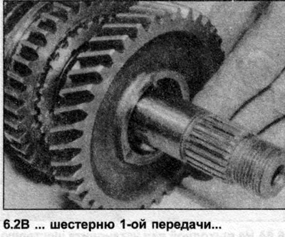
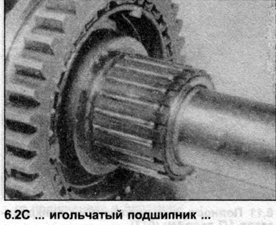
2. Remove the bearing ring and 1st gear, remove the needle bearing and sleeve (photo).
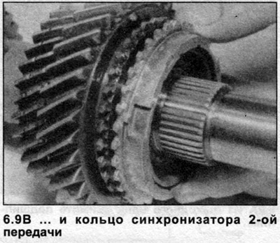
3. Remove the 1st gear synchronizer ring.
4. Place an extractor under the 2nd gear and remove it and the 1st/2nd synchronizer assembly. Remove the 2nd synchronizer ring.
5. Lift the 2nd gear needle bearing, marking its location.
6. The 3rd and 4th gears are firmly seated on the shaft and if they need to be removed, have this work done by an Audi dealer.
7. Assembly is carried out as follows.
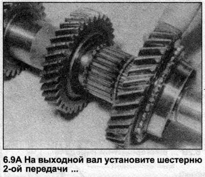
8. Lubricate the 2nd gear needle bearing and install it on the shaft.
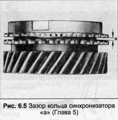
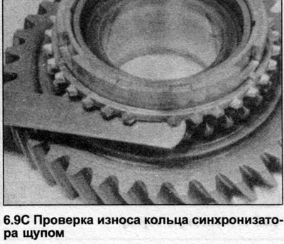
9. Install the 2nd gear pinion on the bearing, place the synchronizer ring on the pinion. Measure the gap as shown in Fig. 6.5, if the gap exceeds the value given in Specifications, the synchronizer ring must be replaced with a new one (photo).
10. If the synchronizer has been disassembled, assemble it as follows. The sleeve and hub may have alignment marks. Install three locking crackers in their grooves, secure the retaining rings. The retaining rings should be separated by 120°, the end of the retaining ring should be inserted into the hole of the locking cracker. If there are no alignment marks on the hub and sleeve, assemble them in any position, the grooves on the hub grooves should face the 1st gear pinion.
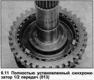
11. Install the synchronizer assembly onto the shaft, with the end of the sleeve with the outer teeth facing the gear. Before pressing the hub down completely, rotate the 2nd gear synchronizer ring so that the grooves in it are aligned with the locking crackers in the synchronizer assembly (photo).
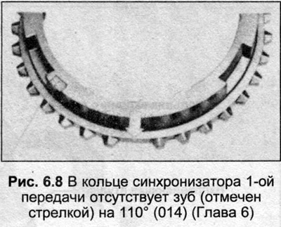
12. Install the 1st gear synchronizer ring, aligning the grooves with the locking dowels in the synchronizer assembly. Late models have a modified synchronizer ring with a missing tooth in three places (Fig. 6.8). The tooth angle on these synchronizer rings has been changed from 120° to 110° to improve the engagement of the 1st gear. This type of ring should only be used on the 1st gear, and if the 1st gear ring is replaced, fit a full tooth 120° type ring, as the modified ring is not available as a repair ring.
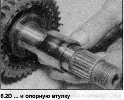
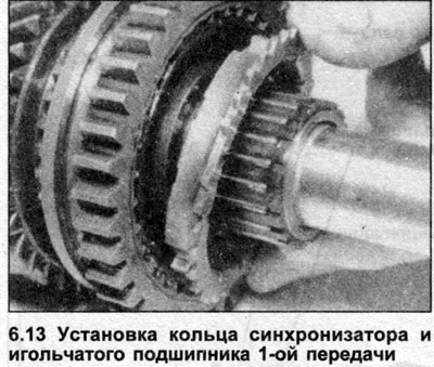
13. Install the 1st gear support sleeve, lubricate the needle bearing and install it on the sleeve (photo).
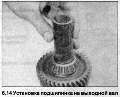
14. Install the 1st gear, then press the inner ring of the 2nd gear tapered bearing (photo).