
2. Install the gear assembly and gear shift fork into the bearing housing.
3. Drive the outer portion of the tapered roller bearing onto the end of the shaft, making sure that the gear selector shaft does not get pinched when doing this.
4. Install the gear control clamp on the gear shift rod, align the hole with the hole in the gear shift rod, insert the roll pin.
5. Install the reverse gear and segment into the bearing housing, then push in the reverse gear shaft.
6. Install the input shaft assembly into the gearbox without the bearing.
7. Pull back the 3/4 shift rod until the 3/4 shift fork fits into the groove in the synchronizer hub sleeve. Move the shift rod to neutral, align the hole in the shift rod with the hole in the fork. Support the free end of the shaft as you did when removing the shift fork and insert the pin.
8. Install the new gasket to the transmission case, slide the bearing carrier with the input and output shaft assemblies to the transmission case. Align the holes and insert the dowel pin. Insert and tighten the bolts.
9. Install the input shaft ball bearing onto the end of the shaft, with the closed side of the bearing housing facing the bearing carrier. Tap the bearing in.
10. Install the thrust washer and snap ring onto the input shaft bearing.
11. Pull back the two gearshift rods until 1st gear and reverse gear are engaged, locking the shafts together. Install the output shaft nut, tighten it to the tightening torque specified in Specifications and lock the nut on the shaft. Move the pickup shafts back to their neutral position and check that both shafts rotate freely.
12. Very carefully pull the 3/4 shift rod out far enough to install the small locking piston. Lubricate the plunger, insert it into the hole, and push the shift rod back in. If the rod is pulled out too far, the synchronizer hub locking crackers may pop out.
13. When installing the shift housing to the carrier housing, use a new gasket.
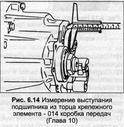
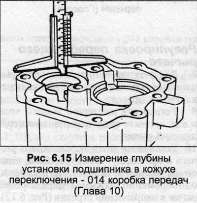
14. If the input shaft bearing or pinion bearing was replaced, it is necessary to calculate the thickness of the new shims that will be installed behind the bearing. To do this correctly, the bearings must be fully seated in their positions, then measure the protrusion of each bearing from the front face of the bearing housing (Fig. 6.14). Then measure the depth into the shift housing for each bearing (Fig. 6.15). Determine the thickness of the shims required by subtracting the bearing protrusion from the depth of the recess and adding 0.3 mm. Once the required thickness has been determined, new shims can be purchased.
15. When installing the shift housing, first check that the gaskets are installed in the housing with the recess towards the spring.
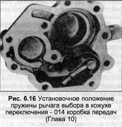
16. Install the spring by placing it inside the selector lever. Compress the spring and insert the inner selector lever into the housing so that the end of the spring is positioned against the end of the housing and the gasket. Move the spring and selector lever into the housing as far as possible (Fig. 6.16).
17. Insert the selector lever pin into the grooves in the gearshift rods, install the gearshift housing in place. Insert the bolts, tighten them to the tightening torque specified in Specifications.
18. Lower the differential into the final drive housing with the crown wheel teeth facing inward. Install the O-ring on the cover, place the cover on the housing. Insert the bolts, tighten them evenly in a diagonal sequence to the tightening torque specified in Specifications.
19. Insert the drive flanges into each side of the differential, tighten the bolts.
20. Fill the gearbox with oil.
[The original source of the article can be found on the website «AudiManual»]