Table of contents: Gear Shift Lever Assembly ↓ Gear shift clutch ↓
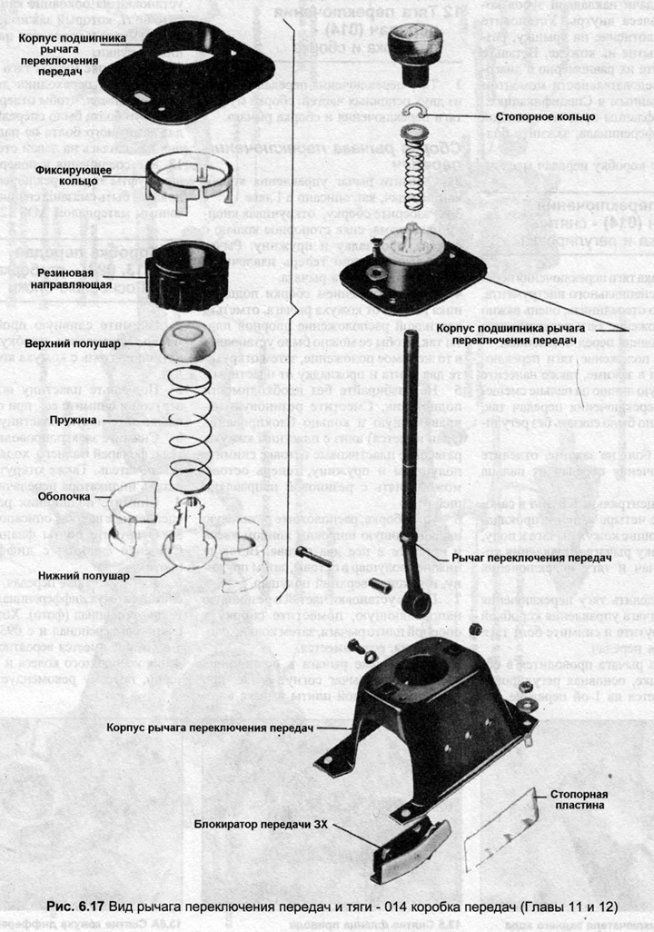
1. The shift rod consists of two main parts: the shift rod coupling assembly and the shift rod lever assembly.
Gear Shift Lever Assembly
2. Remove the gearshift lever as described in Chapter 11.
3. Disassemble the assembly by unscrewing the mechanism button, removing the locking ring from the lever, the gasket and the spring. The control lever can now be removed from the lever bearing assembly.
4. Before separating the lever bearing assembly from the lever housing, mark the position of the support plate with a scriber so that it can be installed in the same position, then remove the two screws and the gasket from the plate.
5. Do not disassemble the bearing unnecessarily. Move the rubber guide and the locking ring (if any) down from the casing plate, spread the plastic frames, remove the half-balls and spring, now the frames can be removed from the rubber guide.
6. When assembling, position the rubber guide with the wide end up and insert the two frames into it. Insert the lower half ball into the frames, then the spring, and finally the upper half ball.
7. After installing the parts into the rubber guide, place the assembly into the lever base plate, then the locking ring if equipped.
8. When inserting the lever into the bearing, note that the lever is bent to the left, when installing the lever support plate into the casing, align the plate with the mark made before disassembly.
Gear shift clutch
9. To disassemble the shift rod coupling, remove the bolt from the end of the holder rod. Mark the position of the adapter on the selector lever, loosen the bolt, remove the shift rod coupling assembly.
10. Remove the ball retainer sleeve from its mounting on the hood side. Remove the bolt that clamps the two side panels together and remove the offset pin and bushings.
11. When assembling the shift rod coupling, the adapter should be installed so that the hole for the clamp bolt is at the front and the groove for the clamp bolt on the shift pin is on the left side.
12. All joints and friction surfaces of the gearshift rod clutch must be lubricated with special lubricant AOS 126 000 05.