2. Pry up the cover plate with a screwdriver and remove it, install a new plate when assembling.
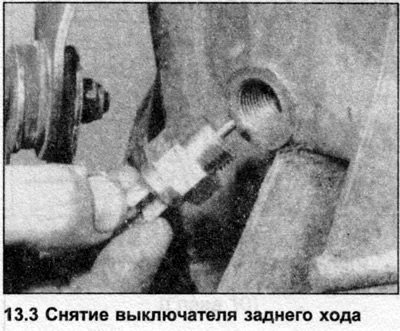
3. Remove the wiring of the reverse light switch, unscrew the switch. Also unscrew the gear indicator switch.
4. Remove the clutch release bearing and shaft as described in Section 5.
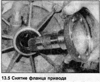
5. Unscrew the drive flange bolts. Remove the flanges from the differential (photo).
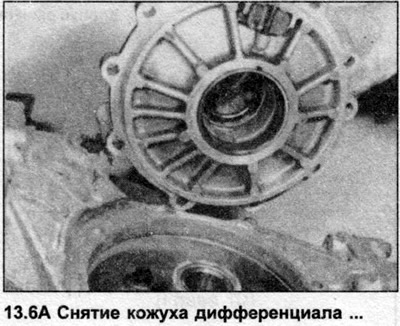
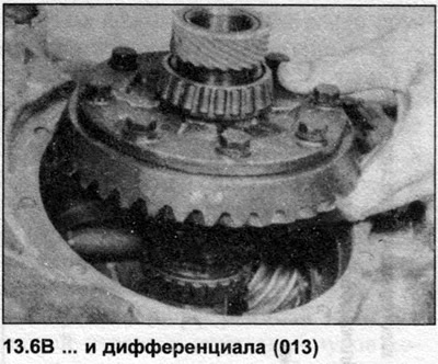
6. On the 013 gearbox, unscrew and remove the differential cover, lift the differential (photo). Although it is possible to remove the differential from the 093 gearbox at this stage, there is a risk of damage to the crown wheel and pinion teeth, so it is recommended to remove the differential after disassembling the gearbox.
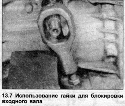
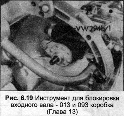
7. Unscrew the bolt at the end of the input shaft, remove the thick gasket. Use special tools to lock the shaft (photo and Fig. 6.19)
8. Remove the shift housing bolts.
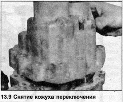
9. Remove the shift housing from the mechanism mounting element, remove the gasket (photo). If the bearing is clamped at the end of the input shaft, an extractor will be required.
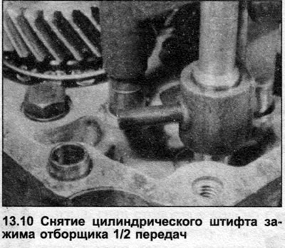
10. Push the roll pin out of the 1/2 gear selector clamp, turn the clamp counterclockwise (photo).
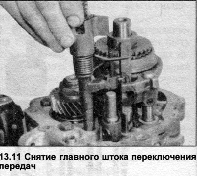
11. Pull the shift rod out to engage 3rd gear, then turn the main shift rod counterclockwise and remove it from the mechanism mounting (photo).
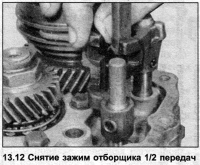
12. Remove the 1/2 gear selector clamp, move the 3/4 gear shift rod to the neutral position (photo).
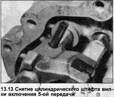
13. Push the roll pin out of the 5th gear shift fork, supporting the rod with a block to prevent damage to the bore in the bearing housing (photo).
14. Engage 5th gear by moving the synchronizer sleeve and 1st gear pinion and extending the 1/2 gear shift rod. The input and output shafts are now locked and the output shaft nut can be loosened. Once the nut is removed, return the mechanisms to neutral.
15. Unscrew the bolts securing the mechanism fastening element to the main gear casing.
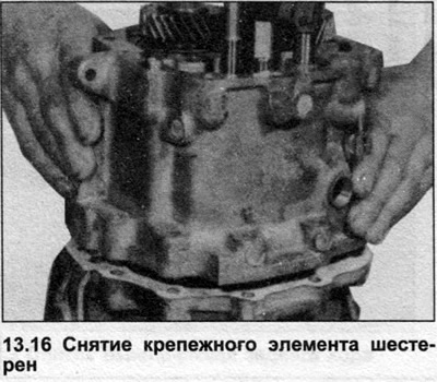
16. Remove the mechanism fastener and gasket, if necessary, knock out the dowel pins (photo). Wrap adhesive tape around the input shaft grooves before removing the mechanism fastener to prevent damage to the seal.
17. Insert an extractor under the 5th gear, remove the 5th gear and synchronizer, part of the 5th gear clutch, and the 5th gear engagement fork.
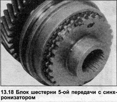
18. Separate the clutch and synchronizer ring from the 5th gear and synchronizer (photo).
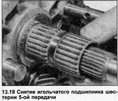
19. Remove the 5th gear needle bearing from the input shaft (photo).
20. Using an extractor, remove the 5th gear driven gear from the output shaft.
21. Remove the 5th gear mechanism thrust washer and inner ring (photo).

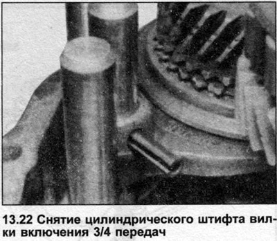
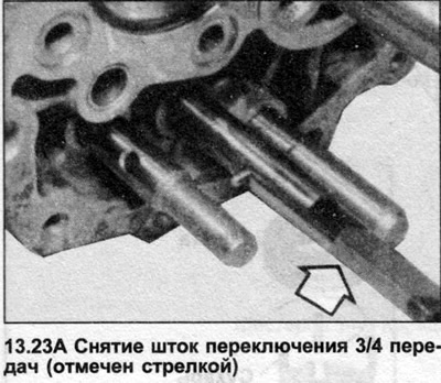
22. Press the roll pin out of the 3/4 shift fork, supporting the shift rod with a block to prevent damage to the bore in the bearing housing (photo).
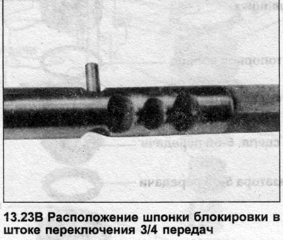
23. Remove the 3/4 shift rod from the mechanism mounting element. Remove the small locking piston from the rod (photo).
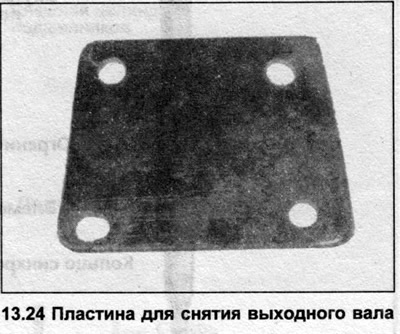
24. The output shaft now needs to be pulled out through the inner bearing ring by 6-8 mm so that the input shaft can be removed. To do this, secure the block and install the inner bearing track with a press or a plate (photo) and long bolts.
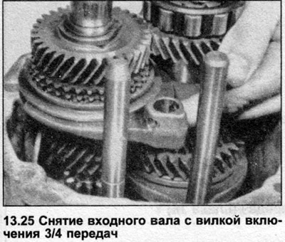
25. Remove the input shaft with the 3/4 gear engagement fork from the mechanism fastening element (photo).
26. Move the gear shift rods to neutral position.
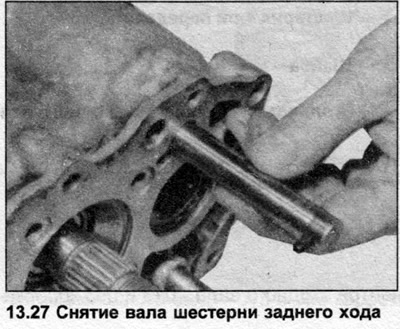
27. Using a soft metal drift, push out the reverse gear shaft and remove the reverse gear (photo).
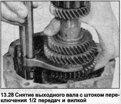
28. Remove the output shaft with the 1/2 gear shift rod and fork (photo).
29. Remove the locking keys from the mechanism fastening element.
30. If necessary, remove the differential on the 093 gearbox (see point 6).