
Table of contents: Removal ↓ Engine separation from AT "09D" ↓ Engine separation from AT "0C8" ↓ Installation ↓
Note: The engine is removed together with the AT and subframe from under the engine compartment (with the front panel installed), and then separated from the transmission.
Removal
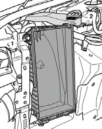
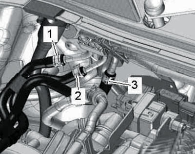
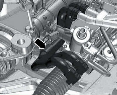
1. Follow the steps described in paragraphs 1-11 Section 4. Please note that on models from 06.2010, the connection of the right lower coolant hose to the radiator is made differently than on earlier models. Therefore paragraph 8 Section 4 should be replaced with the following description: disconnect the connector (3 in the illustration) coolant temperature sensor "G83" at the radiator outlet, disconnect the right lower coolant hose (1) from the radiator and allow the liquid to drain.
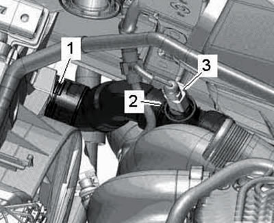
15.1. Connector of sensor G83 (3) and retainer (1) of the right lower hose on the radiator of models from 06.2010.
2. Disconnect the coolant hose (1 in illustration 4.12b).
3. For models before 05.2010, follow the steps in paragraphs 13-15 Section 4.
4. On models from 06.2010, open the cover (arrow in the illustration) terminals 30, unscrew the bolt (1), remove the stud (2) of the positive battery terminal and move it to the side.
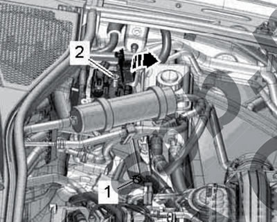
15.4. Bolt (1) and stud (2) for positive battery terminal of models from 06.2010.
5. Follow the steps described in paragraphs 16-19 Section 4. Please note that on models from 06.2010 the power steering pump connections have been changed, so use the resistor instead of Illustration 4.18. illustration.
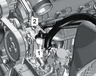
15.5. Power steering pump connections for models from 06.2010.
6. On models from 06.2010, disconnect the air hoses at the locations (2 and 3 in illustration 4.21), loosen the clamps (see illustration) and remove the air hose.
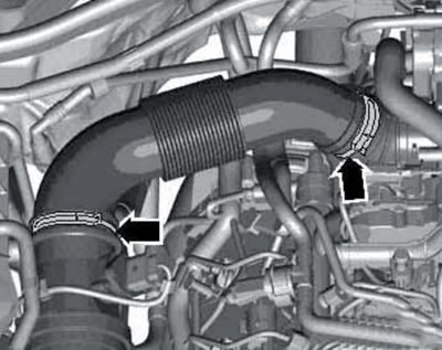
15.6. Air hose clamps for models from 06.2010.
Go to paragraph 12 (paragraphs 7-11 describe actions for models up to 06.2010).
7. Unhook the coolant hose from the air cleaner cover and unhook the hose from the air cleaner housing (1 in the illustration) front differential ventilation.
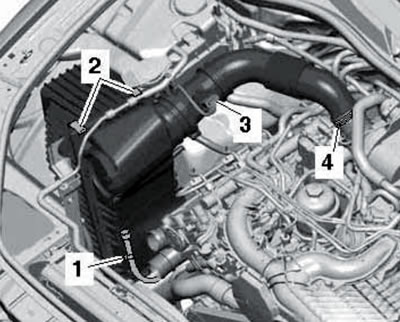
15.7. Air cleaner connections for models before 05.2010.
Disconnect the connector (3) of the MAF sensor "G70", disconnect the air hose from the turbocharger (clamp 4) and release the clamps (2).
8. On models with air suspension, press the retaining ring (1 in illustration 4.24) forward from the connection. Press the ring (2) in the direction of the arrows and remove the ventilation hose (3) from the air cleaner housing. Remove the air cleaner cover and filter element.
9. Working from the wheel arch, squeeze out the air duct (2 in the illustration) from the air cleaner housing (1).
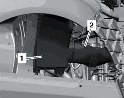
15.9. Air duct (2) on the air cleaner body (1) of models up to 05.2010.
10. Remove the bolts (1 and 2 in the illustration).
15.10. Fastening the air cleaner housing (1) and the washer fluid reservoir neck (2) for models up to 05.2010.
Gently push the washer fluid reservoir neck to the side and remove the air cleaner housing.
11. Loosen the clamps (1-3 in the illustration) and disconnect the air hoses.
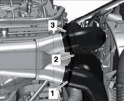
11/15 Air hose clamps for models before 05/2010.
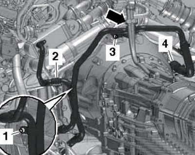
12. Follow the steps in paragraphs 25-28 Section 4. When performing paragraph 27, note that on models from 06.2010 there are two fuel return lines (2 and 3 in the illustration), and both of these lines should be disconnected.
15.12. Supply (1) and return (2 and 3) fuel lines for models from 06.2010.
Additionally, on models from 06.2010 onwards there is no need to remove and disconnect the connector (1 in Illustration 4.2 of Chapter 4) sensor "G448".
13. Disconnect the "G39" lambda probe connector (5 in the illustration), remove the NOx sensor "G295" (4), move the wiring to the side and hang the NOx sensor on the body.
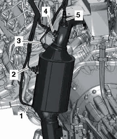
15.13. Lambda probe "G39" (5), NOx sensor "G295" (4) and other sensors.
14. Follow the steps described in paragraphs 29-30 Section 4. On models before 05.2010, disconnect the connector (see illustration).
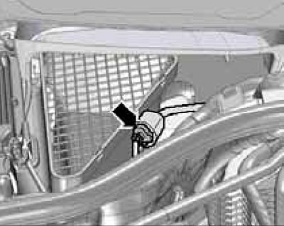
15.14. Electrical wiring connector for models up to 05.2010.
15. Follow the steps in paragraphs 31-35 Section 4, and then separate the exhaust pipe on the clamp (see illustration).
15.15. Exhaust pipe clamp.
16. Remove NOx sensor No. 2 "G687" (3 in the illustration) and remove the wiring harness from the transfer case.
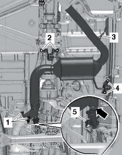
15.16. Connections and fastening of the SCR catalyst.
Disconnect the connector (5) and also remove the electrical wiring. Loosen the clamps (arrows) and remove the "N474" AdBlue injector. Loosen the nuts (1), remove the bolts (2 and 4), and remove the SCR catalytic converter.
17. On models up to 05.2010, unscrew the bolts securing the rear propeller shaft to the transfer case (see illustration 4.36). Slide the rear propeller shaft assembly toward the rear final drive (CV joints can be moved in the axial direction) and tie up the end of the cardan shaft.
18. Remove the soundproofing panel bracket (see illustration 4.37) and remove the exhaust pipe bracket from the side member (see illustration 4.39).
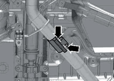
19. Unscrew the exhaust gas temperature sensor No. 4 "G648" (see illustration).
15.19. Exhaust gas temperature sensor No. 4 "G648".
20. Disconnect the hoses (see illustration 4.41), going to the pressure difference sensor "G505" from the pressure pipes of the diesel particulate filter.
21. Disconnect the steering gear wiring connector (see illustration 4.42).
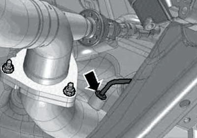
22. On models from 06.2010, remove the rear propeller shaft (see Chapter 7). Then squeeze the tip (1 in the illustration) selector cable from the selector mechanism lever with lever No. 80 - 200, unscrew the bolts (2) and remove the cable together with the support from the AT.
15.22. Selector cable separation from AT "0C8".
Do not bend the selector cable.
23. Follow the steps described in paragraphs 43-51 Section 4. Paragraph 45 applies only to models up to 05.2010.
24. Make sure that all wiring lines and connectors between the engine, AT, subframe and body are disconnected.
25. On models prior to 05.2010, disconnect the selector cable from the AT "09D" as described in paragraphs 52-54 Section 4.
26. Finally lower the power unit, together with the subframe, from under the car, guiding it so as not to damage any parts. Direct the suspension struts behind the side members.
Engine separation from AT "09D"
27. Follow the steps described in paragraphs 55-58 Section 4.
28. Remove the bolts (1 and 2 in the illustration) and remove the turbocharger thermal protection bracket.
15.28. Fastening the turbocharger heat shield.
29. Give the nuts (see illustration 4.61) and remove the primary catalytic converter with the diesel particulate filter.
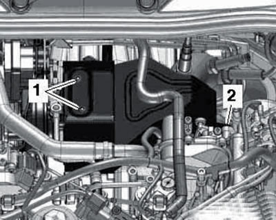
30. Move the coolant hoses aside (see illustration).
15.30. Coolant hoses.
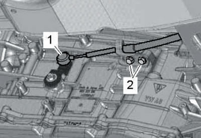
31. Loosen the clamp (2 in the illustration), pull out the retainer (4) and disconnect the coolant hoses.
15.31. Fastening of coolant hoses (2 and 4), AT ventilation hose (arrow) and bolts (1 and 3) of the left coolant pipe.
Move the AT ventilation hose (arrow) to the side, unscrew the bolts (1 and 3) and separate the left coolant pipe from the rear side of the AT.
32. Follow the steps described in paragraphs 64-67 Section 4.
33. Remove the generator (1 in the illustration) and starter (see illustration 4.72), as described in Chapter 5.
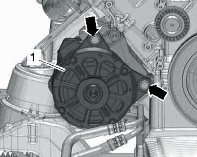
15.33. Starter mounting bolts (arrows) (1).
34. Insert the guide pin of the T40058 adapter with a larger diameter (2 in illustration 4.73a) outward, and with a smaller diameter (2) - into the adapter. Hold the crankshaft from turning by installing the adapter assembled in this way on the center of the crankshaft pulley (see illustration 4.73b).
35. Remove the cover (see illustration) and follow the steps described in paragraphs 74-78 Section 4.
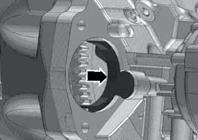
15.35. Cover in the starter mounting hole.
Engine separation from AT "0C8"
36. Secure the VAS6131/13-7 support to the conical holes on the front side of the engine using the M 10x45 bolt (1 in illustration 4.55) and nuts (2), and then fix this support on the coordinate table.
37. Install supports from sets VAS6131/10, -/12, -/13 and -/14 under the front side of the AT and the front propeller shaft, as shown in the illustration.
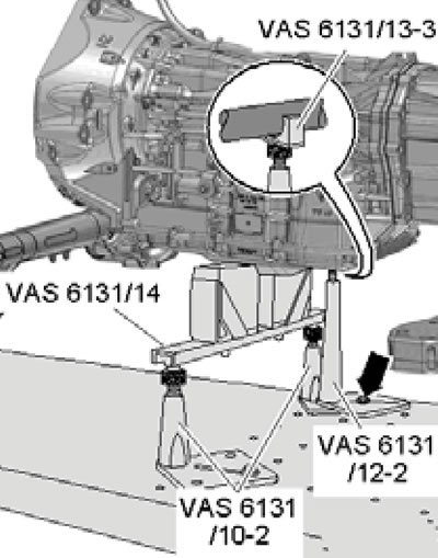
15.37. Supports for AT "0C8" and front propeller shaft.
Secure the VAS6131/12-2 support with an M10 x 35 bolt (arrow) and washer.
38. Remove the bolts on the particulate filter and primary catalytic converter brackets (see illustrations 4.58a-b).
39. Remove the brown wiring connector from the bracket (2 in the illustration) exhaust gas temperature sensor No. 3 "G495" and disconnect it.
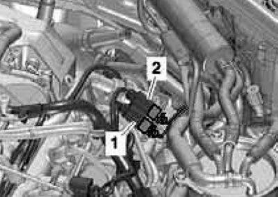
15.39. Electrical wiring connectors on the bracket.
Move the wiring to the side.
40. Follow the steps described in paragraphs 28-31.
41. Follow the steps described in paragraphs 65-67 Section 4.
42. Follow the steps described in paragraphs 33-34.
43. Remove the cover (see illustration 15.35).
44. Mark the position of the torque converter relative to the drive disc. Then unscrew the bolts (only 6 pcs.) fastening the torque converter through the opening for the starter (see illustration 4.74), holding the crankshaft from turning by its central bolt. To access each subsequent pair of torque converter mounting bolts, rotate the crankshaft 120°.
45. Remove the bolts (3-10 in the illustration) aT fastenings to the engine.
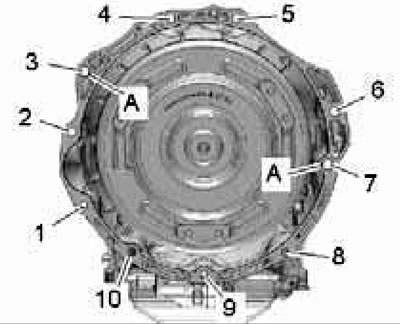
15.45. Bolts for fastening AT "0C8" to the engine:
A - Centering bushings;
1 - Bolt M10x70, 65 Nm;
2 - Bolt M 10x90, 65 Nm;
3...5, 7 - Bolt M12x80, 80 Nm;
6 - Bolt M12x70, 80 Nm;
8...10 - Bolt M10x70, 45 Nm.
Separate the AT from the engine by moving the coordinate table apart: the engine is supported by four supports on one part of the table, and the AT is also supported by four supports on the other part of the table. At the same time, separate the torque converter from the drive disk through the opening for the starter.
46. Follow the steps described in paragraphs 77-78 Section 4.
Installation
Note: Place the hoses and wiring in the same position as they were before removal; install all clamps and ties in their original places.
47. Make sure that the AT centering bushings are present in the cylinder block (And in the illustrations 4.75 and 15.45), install them if necessary. In addition, the centering sleeve must be installed in the crankshaft (see illustration 4.79).
48. Install a torque converter in the AT (om. Chapter 6) and make sure it is located at a distance (And in the illustration 4.80) from the torque converter flange. For the AT "09D", this distance should be 22 mm, and for the AT "0C8" - 23 mm. If the torque converter is not fully installed, this distance will be approximately 10 or 11 mm (for the AT "09D" or "0C8", respectively).
49. Follow the steps described in paragraphs 81-82 Section 4.
50. Further installation is carried out in reverse order. Please note the following features.
51. The tightening forces for the AT fasteners to the engine are indicated in the captions to illustrations 4.75 and 15.45. Tighten other threaded fasteners to the following torques.
Note: Torques are given with a tolerance of ±15% for lightly lubricated, phosphated or black fasteners. Do not remove factory grease from fasteners. Additional lubrication with engine or transmission oil is permitted, but not with graphite-containing lubricants.
- Positive battery terminal stud - 15 Nm.
- Mass connection (2 in illustration 4.31) - 9 Nm.
- Mass connection (2 in illustration 4.31) in the air intake chamber - 9 Nm.
- Other fasteners M6/M7/M8/M10/M12 - 9/15/20/40/65 Nm.
52. Please note the information provided in paragraphs 85-87 Section 4.