
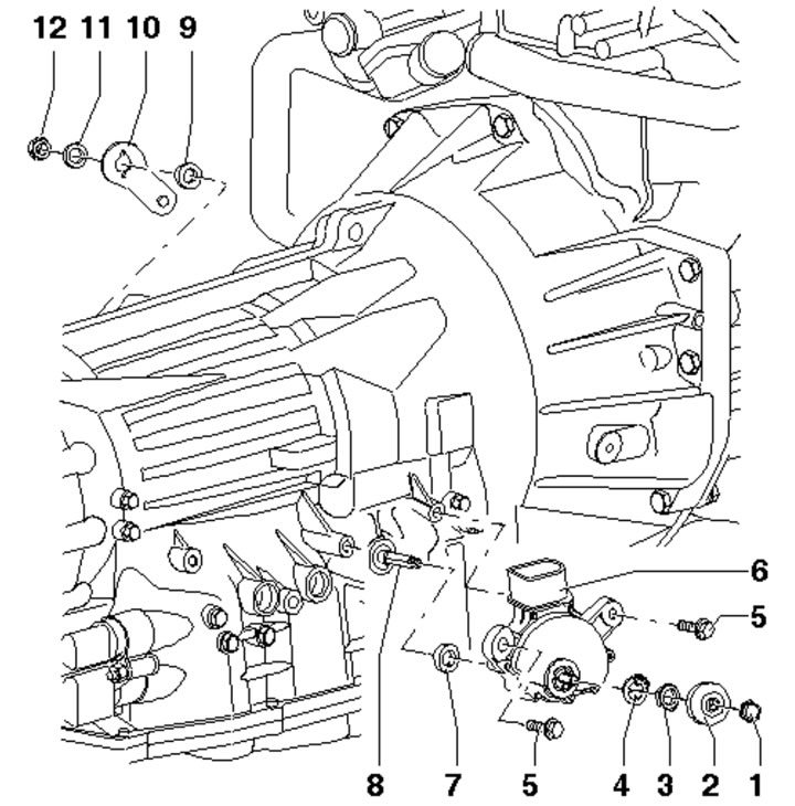
8.1. AT selector mechanism installation details:
1 - Nut, 12 Nm;
2 - Overlay;
3 - Nut. 7 Nm;
4 - Retainer;
5 - Bolt, 6 Nm;
6 - D/V of the selected AT mode "F125";
7 - Right selector shaft seal;
8 - Selector shaft;
9 - Left selector shaft seal;
10 - Selector mechanism lever;
11 - Washer;
12 - Nut, 12 Nm.
2. The sequence of actions for providing access to the "F125" sensor and the selector lever is described in Section 5.