
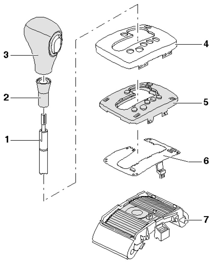
7.1. Selector lever installation details 1. Selector lever; 2. Lever bushing 1; 3. Lever handle 1; 4. Overlay; 5. Insert with lever position marks 1; 6. Printed circuit board with built-in D/V manual switching; 7. Sliding cover with built-in magnet D/V manual switching
Selector lever handle
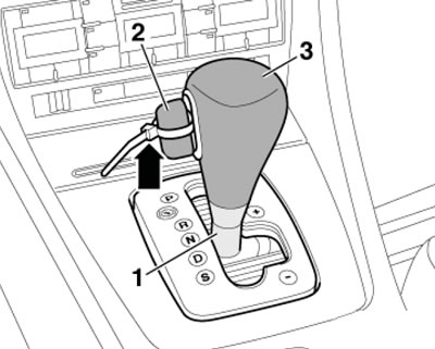
2. Set the selector lever to position "D", turn the sleeve (1 in the illustration) counterclockwise and press it down until it stops.
7.2. Removing the handle
3. Gently pull out the lock release button (2 in illustration 7.2) from the handle (3) so that you can pass a clamp between them, and secure the button with the clamp.
Note: Do not pull the button out further, otherwise the handle may be damaged.
4. Remove the handle by pulling it upwards.
5. Installation is carried out in the reverse order of dismantling the components.
Overlay
6. Remove the selector lever handle (see subsection above).
7. Open the ashtray and remove the trim panel in the direction of the arrows (see illustration).
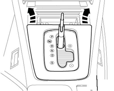
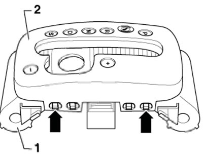
7.7. Removing the facing panel
8. Press the four clamps (arrows in the illustration) and lift the cover (1) together with the guide. Disconnect the connector on the guide side.
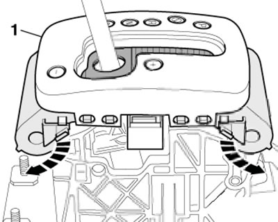
7.8. Removing the overlay
9. Installation is carried out in the reverse order of dismantling the components.
D/V manual switching
10. Remove the cover (see subsection above).
11. Press in 4 locking hooks (arrows in the illustration) and pull the cover (2) out of the guide (1).
7.11. Removing the cover from the guide
12. Make sure the two magnets (arrows in the illustration) securely fastened in the transverse direction of the sliding cover.
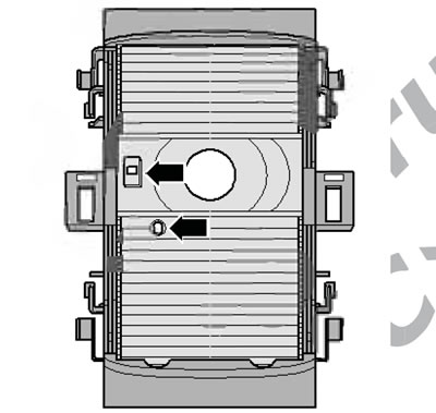
7.12. Magnets
13. Unhook the printed circuit board (1 in the illustration) with built-in D/V manual switching from the cover (2).
14. Installation is carried out in the reverse order of dismantling the components.
(The original article is available on the online resource: audimanual.ru)