
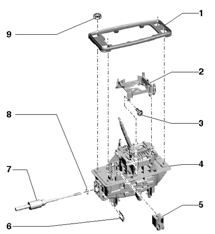
8.1. Selector mechanism installation details 1. Compaction; 2. Adapter; 3. Bolts, 4 pcs., 2 Nm; 4. Assembling the selector; 5. Solenoid valve for locking the selector lever; 6. Retainer; 7. Selector cable; 8. Sealing ring, subject to replacement; 9. Nuts, 4 pcs., 8 Nm
2. Remove the selector lever cover (see Section 7).
3. Remove the climate control panel (see Chapter 3).
4. Remove the ashtray and disconnect the selector lever lock solenoid valve connector.
5. Lift the retainer (And in the illustration) and pull the locking cable in the direction of the arrow.
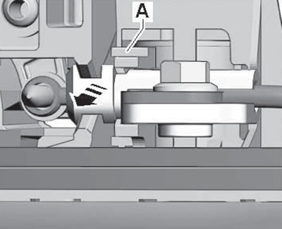
8.5. Locking cable retainer
6. Set the selector lever to position "D". Insert the T40031 key (see illustration) through the hole in the selector mechanism and loosen the clamp bolt on the back of the selector lever by about 1 turn.
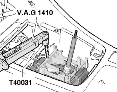
8.6. Loosening the clamp bolt
7. Release the fasteners (2 and 3 in Illustration 5.5 Chapter 2) and remove the rear sound insulation. Remove the center tunnel crossbars (see illustration).
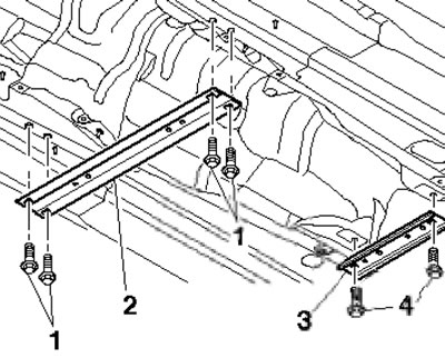
8.7. Central tunnel cross members
8. Loosen the clamps (see illustration 17.25 Chapter 4) and disconnect the exhaust pipes, remove the heat-protective casing over the pipes.
Note: Do not bend the flexible section of the exhaust pipe more than 10°.
9. Pull out the lock (1 in the illustration) selector cable to the side and pull the cable (2) out of the selector mechanism. Do not bend the cable.
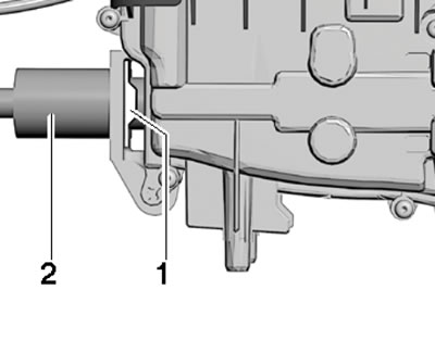
8.9. Removing the selector cable
10. Give the nuts (arrows in the illustration). Have an assistant squeeze the latches (1 and 2) inwards and remove the selector assembly downwards.
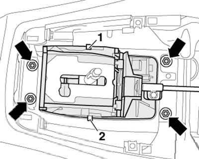
8.10. Selector assembly mounting bolts
Note: If the locking pins are broken, the selector assembly will need to be replaced. Any parts that fall into the selector mechanism will lock it.
11. Installation is carried out in the reverse order of dismantling the components.