
Note: The description is given using 2.0 TFSI AWD models as an example.
1. Turn on the AT mode "N".
2. Disconnect the negative battery cable (see Chapter 5) and remove the decorative engine cover (see chapter 2).
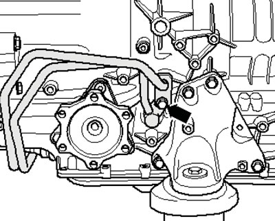
3. Unscrew the bolt (arrow on the illustration) expansion tank mounts, disconnect the low coolant level sensor connector on the bottom of the tank and set the tank aside without disconnecting the coolant hoses from it.
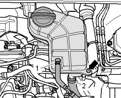
3.3. Fastening the expansion tank
4. Remove the bolts (4-6 in Illustration 5.64b Chapter 2) fastening the AT to the engine from the engine compartment.
5. Remove the rubber seals from the mounting flanges of the front wings, install compensation plates T40045 on both sides between the wing and the body panel to avoid damaging the wings with the support bracket 10-222A (see illustration 16.6 Chapter 2).
6. Install the 10-222A support bracket with 10-222/3 adapters on the wing mounting flanges, insert the hooks into the engine lifting eyes and unload the power unit supports by slightly lifting the engine (see illustration 2.4 Chapter 6).
7. Remove both front wheels. On models with independent/additional heating, unscrew the bolts (arrows in illustration 5.4 Chapter 2) its exhaust pipe from the soundproofing screen.
8. Release the fasteners (1-3 in Illustration 5.5 Chapter 2) and remove the front and rear sound insulation.
9. Remove the bolts (arrows in illustration 5.6 Chapter 2) and remove the sound insulation bracket.
10. Remove the thermal insulation of the left drive shaft (see illustration 5.43 Chapter 2). Separate both drive shafts from the AT (see Chapter 8).
11. Loosen the clamp (see illustration 17.3 Chapter 4) and pull back the exhaust pipe.
Note: Do not bend the flexible section of the exhaust system more than 10°.
12. Remove the bolts (arrows in illustration 17.37 Chapter 2) fastening the exhaust pipe to the catalytic converter, loosen the nut (1) on the front exhaust pipe bracket and remove it.
13. Remove the heat shield (1 in the illustration) cardan shaft, separate the shaft from the AT (see Chapter 8) and slide it toward the rear differential. The joints can move axially. Tie the propeller shaft to the underbody.
3.13. Heat shield of the cardan shaft
14. Press the hinge socket (1 in the illustration) selector cable from the selector shaft lever. Mark the position of the selector cable bracket, unscrew the bolts (arrows) and remove the bracket. Move the selector cable to the side.
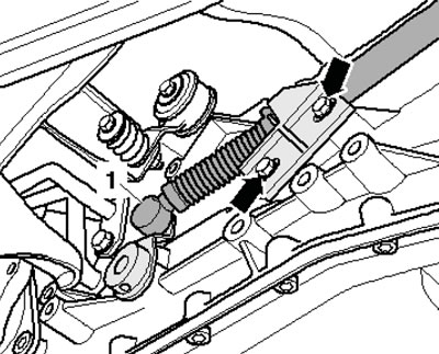
3.14. Selector cable on selector shaft
15. Disconnect the AT wiring connector by turning it counterclockwise to release the lock.
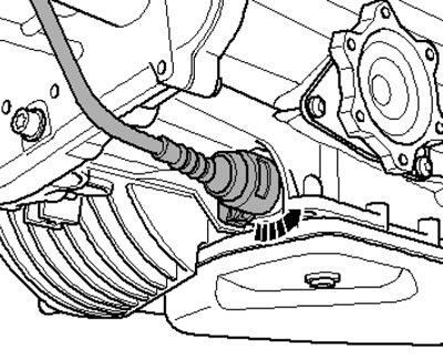
3.15. AT wiring connector
16. Give the nuts (1 and 2 in Illustration 29.8 Chapter 2) and disconnect the ATF tubes. Remove the ATF tube holder (arrow).
17. Disconnect the ATF pipes (1 and 2 in the illustration) on the right side of the AT. Separate the ATF pipes going to the ATF radiator and remove the bracket (3) of the pipes on the lower side of the AT.
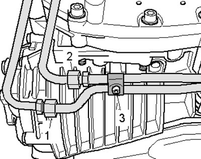
3.17. ATF pipe bracket
18. Unscrew the bolt (arrow on the illustration) and remove the ATF tubes from the AT.
3.18. ATF tube mounting bolt
19. Remove the bolts (see illustration 16.15 Chapter 2) anti-roll bar mounts on both sides.
20. Remove the remaining bolts (1-3 and 8-11 in Illustration 5.64b of Chapter 2) fastening the AT to the engine. Leave bolt 7 screwed in by hand.
21. Remove the starter (see Chapter 5).
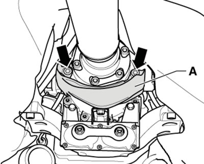
22. Turning the crankshaft clockwise, unscrew the three torque converter mounting bolts (see illustration).
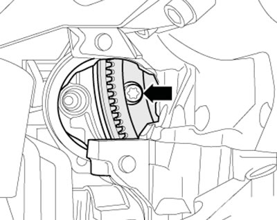
3.22. Torque converter mounting bolt
23. Attach the AT locking device to the transmission jack (see illustration). Secure the jack with the installed locking device to the AT and slightly raise the AT on the jack.
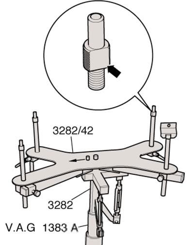
3.23. Device for removing AT
24. Remove the bolts (arrows in illustration 17.26 Chapter 4) left and right supports of the AT.
25. Remove the heat shield of the left AT support and remove the left and right AT supports as an assembly (see illustration 17.28 Chapter 4).
26. Unscrew the remaining bolt securing the torque converter to the engine, pull the torque converter away from the engine and at the same time move the torque converter off the drive disk with a screwdriver so that it does not fall. Lower the torque converter on the jack.
27. If necessary, remove the torque converter. Otherwise, fix it in the AT housing using two strips (see illustration).
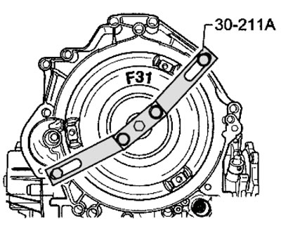
3.27. Fixing the torque converter
28. Before installing the AT, make sure that the torque converter is recessed into its housing at a distance of at least 19 mm (see illustration 29.34 Chapter 2).
29. Installation is carried out in the reverse order of dismantling the components. Use new self-locking fasteners. Finally, correct the ATF level (see Chapter 1).