
Note: The description below is for models with 1.8T engine; removal and installation of manual transmission on other models is carried out in a similar way (for more information, see Chapter 2 for engine removal).
1. Disconnect the negative cable from the battery (see Chapter 5).
2. Remove the upper decorative engine cover.
3. Remove the rubber seals from the mounting flanges of the front wings, install compensation plates T40045 on both sides between the wing and the body panel to avoid damaging the wings with the support bracket 10-222A (see illustration 16.6 Chapter 2).
4. Install the 10-222A support bracket with 10-222/3 adapters on the wing mounting flanges, insert the hooks into the engine lifting eyes and unload the power unit supports by slightly raising the engine (see illustration).
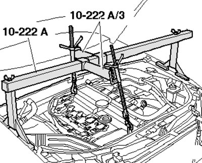
2.4. Installation of the 10-222A device
5. On models with independent/additional heating, unscrew the bolts (arrows in illustration 5.4 Chapter 2) its exhaust pipe from the soundproofing screen.
6. Release the fasteners (1 and 2 in Illustration 5.5 Chapter 2) and remove the front sound insulation.
7. Remove the fasteners and separate the soundproofing bracket (see illustration).
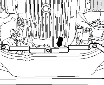
2.7. Fastening the soundproofing bracket
8. Remove the heat shield of the right drive shaft from the manual transmission (see illustration), separate both drive shafts from the manual transmission (see Chapter 8).
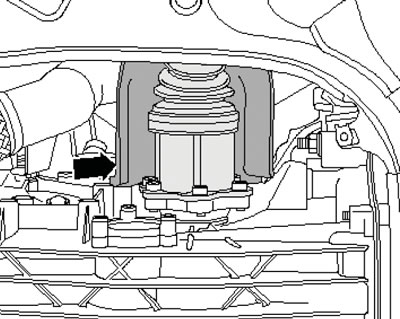
2.8. Right drive shaft heat shield
9. Loosen the clamp (see illustration 16.6 Chapter 4), slide it back and separate the exhaust pipe.
Note: Do not bend the flexible section of the front exhaust pipe more than 10°.
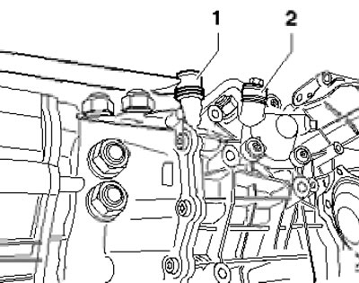
10. Unscrew the bolt (1 in the illustration) and nut (2), separate the front exhaust pipe bracket.
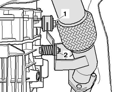
2.10. Fastening the exhaust pipe bracket
11. Support the manual transmission with the VAG1383A transmission jack, having first installed a wooden block between them (see illustration).
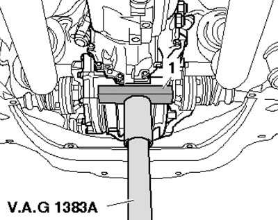
2.11. Installing a support under the manual transmission
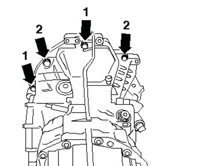
12. Remove the bolts (1 in the illustration), and then the bolts (2) on the crossmember. Loosen the two nuts (3) and remove the crossmember.
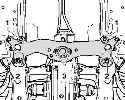
2.12. Fastening of the central tunnel crossmember
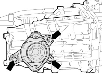
13. Slightly lift the manual transmission on the transmission jack, unscrew the three lower bolts securing the manual transmission to the engine (see illustration) and lower the manual transmission on the jack. If necessary, separate the starter from the power unit without disconnecting the electrical wiring from it (see chapter 5).
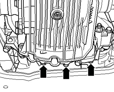
2.13. Lower bolts for fastening the manual transmission to the engine
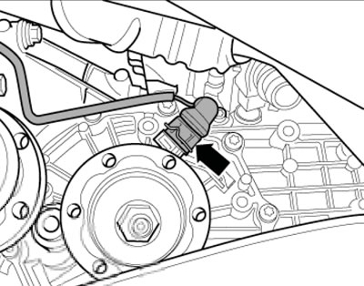
14. Disconnect the D/W reversing light connector (see illustration) and move the electrical wiring to the side.
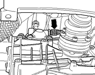
2.14. Reverse light D/W connector
15. If available, disconnect the speedometer sensor connector (see illustration) on the left side of the manual transmission.
2.15. Speedometer sensor connector
16. Unscrew the tie rod mounting bolt (2 in the illustration) gear selection and push rod bolt (1).
2.16. Gear shift mechanism rods on manual transmission
17. Give the nut (1 in the illustration) and separate the gear selector lever (2) from the gear selector shaft.
2.17. Removing the gear selector lever
18. Unscrew the upper bolts securing the manual transmission to the engine (see illustration).
2.18. Upper bolts for fastening the manual transmission to the engine
19. To remove the 01E manual transmission, Audi service stations use support 3282 with adjusting plate 3282/12, installed on a transmission jack (see illustration). This support is designed for reliable mounting of the manual transmission on the jack.
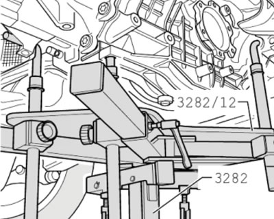
2.19. Support for removing the manual transmission
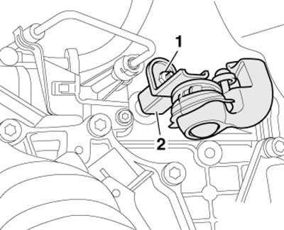
20. Install a support for removing the manual transmission, secure it to the jack and to the manual transmission. Unscrew the remaining bolts securing the manual transmission to the engine, and carefully move the manual transmission away from the engine so that you can access the clutch slave cylinder. Separate the slave cylinder from the manual transmission (see illustration) and hang it on a wire without disconnecting the hydraulic lines from it. Lower the manual transmission on the jack.
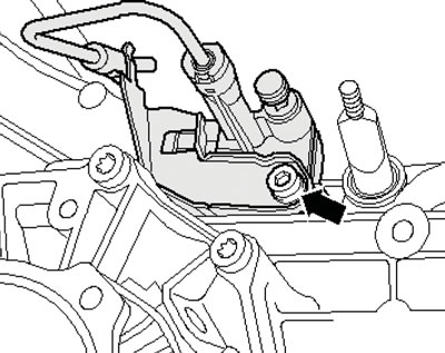
2.20. Fastening the clutch slave cylinder
21. If a new manual transmission is to be installed, transfer the support from the removed manual transmission to it (see illustration).
2.21. Manual transmission support
22. Installation is carried out in the reverse order of dismantling the components. Use new self-locking nuts and bolts, replace seals and gaskets. Please note the following features.
23. Clean the input shaft splines and (if an old clutch is used) hub splines. Remove any corrosion and apply a very thin layer of grease to the splines. Do not lubricate the guide bushing.
24. If the clutch bearing is worn, replace it.
25. Lightly lubricate the contact surface of the actuator rod and clutch release lever with copper grease (arrow B in the illustration). Raise the manual transmission so that the clutch slave cylinder with the pipe bracket can be installed. Insert the slave cylinder (1) into the opening in the manual transmission housing without tilting (arrow A) and insert it into the slot (arrow B) on the clutch release lever (3).
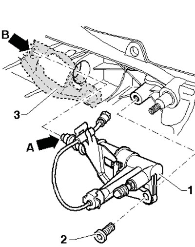
2.25. Features of installation of the clutch slave cylinder
Note: If the slave cylinder is installed at an angle, there is a risk that the slave rod (A) will not be guided through the clutch release lever. Secure the slave cylinder with a new bolt (2).
26. When joining the manual transmission and the engine, you can slightly rotate the crankshaft to align the splines.
27. When tightening the manual transmission fasteners to the engine, pay attention to the different lengths and diameters of the bolts (see section "Removal and installation the engine").