



Note: The description is given using the example of a 6-speed manual transmission 01E/01A. The gearbox is placed in a cast housing, attached to the rear side of the cylinder block. The manual transmission housing is equipped with holes for draining, checking and adjusting the oil level, closed by plugs (see illustration 4.59a Chapter 1).
To identify the manual transmission in places (1 and 2 in illustration 1.1) there is a letter code and a serial number, and in place (3) is its name. Letter code (for example, GBA) and the following 6-digit serial number are additionally indicated on the vehicle data stickers (see "Introduction"). Name of the manual transmission (for example, 01E) occupies the first three positions in the alphanumeric designation.
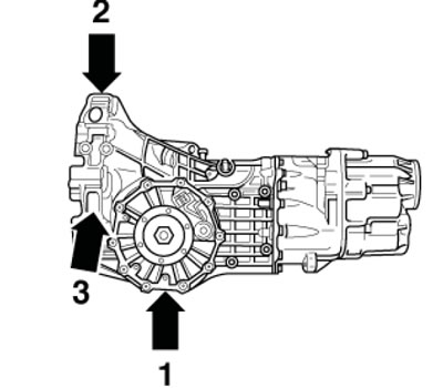
1.1. Manual transmission designations
Rotation is transmitted from the engine crankshaft (1 in illustration 1.2) through the clutch assembly (2) to the primary shaft (4) of the manual transmission (3). The primary (drive) shaft is equipped with splines on which the driven clutch disc is installed. From the primary shaft, on which all 7 driving gears are located, rotation is transmitted to the secondary (driven) shaft of the manual transmission, on which the driven gears of all gears are also located. From the secondary shaft, rotation is transmitted through the cardan shaft to the differential and drive shafts. Free rotation of the differential satellites on their axles allows the inner wheel to rotate more slowly than the outer one when cornering. The primary and secondary shafts of the box are located parallel to each other, as well as parallel to the crankshaft and cardan shafts. The intermediate gear of the reverse gear is located on a separate shaft. The gears of the 5th and 6th gears are covered with a separate cover on the end of the manual transmission housing.
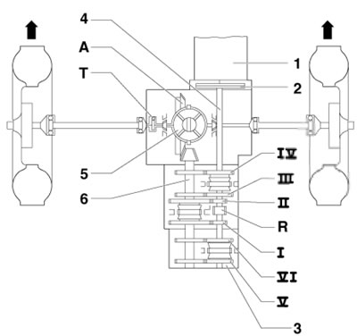
1.2. Torque transmission diagram (using FWD models as an example) 1. Engine; 2. Clutch; 3. Manual transmission; 4. Input (primary) shaft; 5. Differential; 6. Day off (secondary shaft); I-VI. Leading gears of the corresponding transmissions; R. Reverse gear pinion; A. Main gear; T. Electronic speedometer drive (speed sensor)
Gear shifting is performed using a gear shift lever mechanism installed on the floor of the passenger compartment. The mechanism consists of a set of shift forks, with the help of which the sliding clutches of the synchronizers move along the shaft, locking the gears of the corresponding gears. The parts of the gear shift mechanism drive are shown in Figure 1.3.
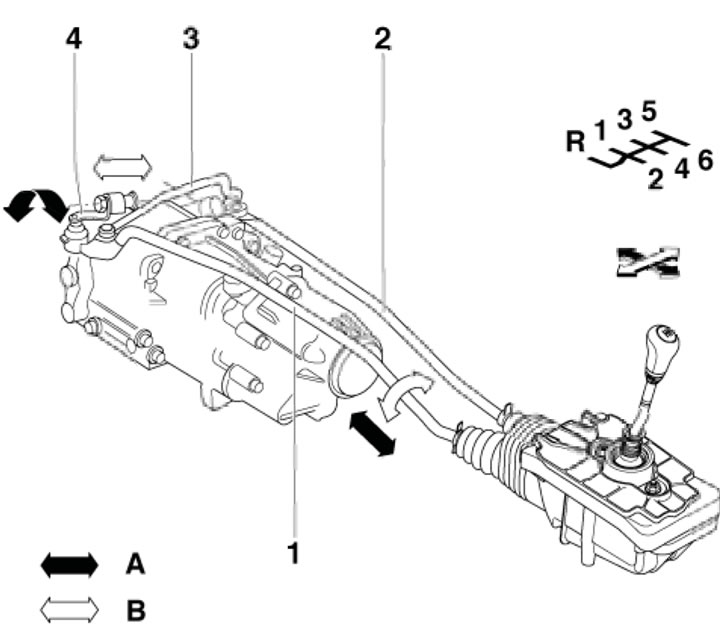
1.3. Gear shift mechanism operation diagram 1. Gear selection rod; 2. Front traction; 3. Connecting rod; 4. Selector shaft lever; A. Movement of the gear shift mechanism; B. Movement of the gear selection mechanism
[The original material is located on the website: audimanual.ru]