
Table of contents: Removal and installation the front… ↓ Removal and installation the drive… ↓
1. The installation details of the drive disc and crankshaft seals are shown in the illustrations.
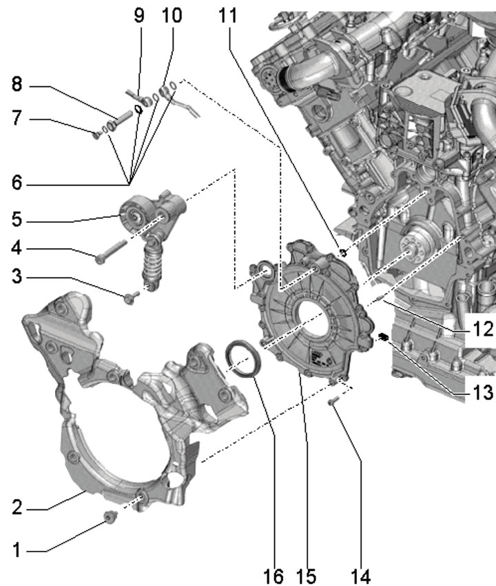
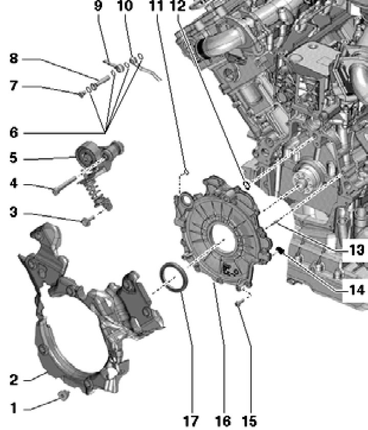
38.1a. Front crankshaft seal installation details (using CCFA/CCFC engines as an example):
1 - Bolt, 6 Nm;
2 - Flange cover 16;
3, 4 - Bolts, see illustrations 37.1a-b;
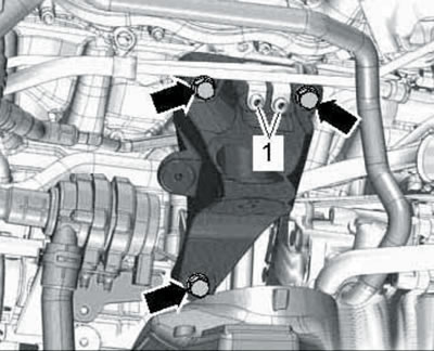
5 - Drive belt tensioner;
6 - Sealing rings, subject to replacement;
7 - Threaded plug;
8 - Hollow bolt;
9/10 - Right/left oil supply line to the turbocharger;
11 - O-ring, subject to replacement, not present on the BTR engine;
12 - O-ring, must be replaced;
13 - Centering sleeve, 2 pcs.;
14 - Sealing element, 2 pcs., subject to replacement;
15 - Bolt, 9 Nm;
16 - Front sealing flange;
17 - Front crankshaft oil seal.
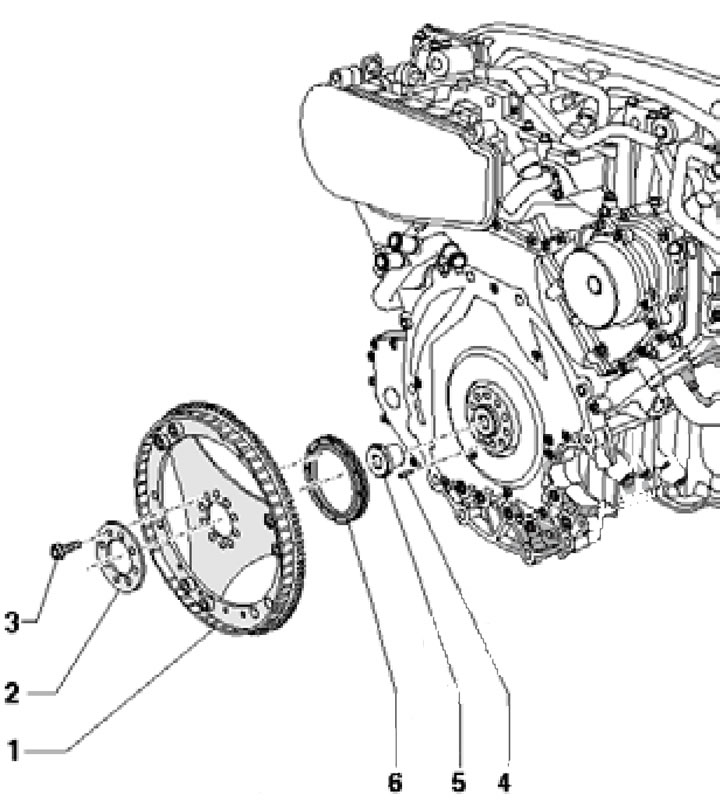
38.1b. Installation details of the drive disc and rear crankshaft oil seal (bTR engine):
1 - Drive disk;
2 - Washer;
3 - Bolt, to be replaced, 30 Nm then tighten to an angle of 90°;
4 - Centering sleeve of the drive disk;
5 - Torque converter centering sleeve, inserted into the crankshaft;
6 - Rear crankshaft oil seal.
38.1 p. Details of the installation of the drive disk and rear crankshaft oil seal (cCFA/CCFC engines):
1 - Bolt, to be replaced, 30 Nm then tighten to an angle of 90°;
2, 4 - Washer;
3 - Drive disk;
5 - Rotor of the CKP sensor;
6 - Rear crankshaft oil seal;
7 - Torque converter centering sleeve, inserted into the crankshaft;
8 - Centering sleeve of the drive disk.
2. Replacing the front oil seal is done in the same way as on 1st generation 3.0 TDI engines (see Section 7). The only difference is the use of the T40048/3 bushing instead of the T40048/4 bushing. The features of removing the crankshaft pulley of 4.2 TDI engines are described in Section 37.
Removal and installation the front sealing flange
3. Remove the drive belt tensioner and crankshaft pulley (see Section 37).
4. On CCFA/CCFC engines, remove the "V400" EGR cooler pump and the left EGR pipe (see Chapter 4). Disconnect the PCV tube from the hoses (arrows in the illustration).
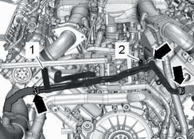
38.4. Clamps (arrows) for fastening hoses to the PCV pipe.
5. Remove the center front coolant pipe and the lower front coolant pipe (see Chapter 3).
6. Remove the right engine mount (see Section 36). Unscrew the bolt (1 in illustration 36.5), loosen the clamp (5) and remove the left air tube.
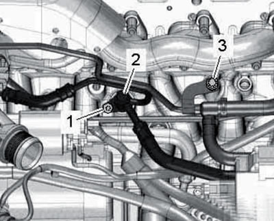
7. Remove the bolts (1 in the illustration) fastening the oil and coolant supply lines to the turbocharger.
38.7. Fastening (1) of turbocharger supply lines.
8. Unscrew the bolt (1 in the illustration 35.50), loosen the clamp (arrow) and remove the right air tube together with the air hose forward.
9. Unscrew the bolts and remove the right engine mount bracket (see illustration 35.53).
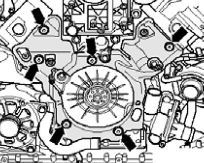
10. Remove the bolts (1 and 3 in the illustration) and disconnect the coolant pipes (2) from the cylinder block.
38.10. Bolts (1 and 3) for fastening coolant pipes (2).
11. Remove the bolts (see illustration) and remove the front sealing flange cover, paying attention to the feed oil lines.
38.11. Fastening the front sealing flange cover.
12. Loosen the front sealing flange mounting bolts in a diagonal order. Then completely unscrew them and carefully separate the flange from the engine (the flange is held in place by sealant). Remove the rear crankshaft oil seal from the flange.
13. Using a plastic drill brush, remove any remaining sealant from the flange grooves and from the flange/engine mating surfaces. Clean the mating surfaces of oil and grease.
14. On CCFA/CCFC engines, install sealing elements (2 and 4 in the illustration) and sealing rings (1 and 3).
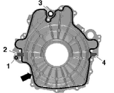
38.14. CCFA/CCFC engine front flange seal parts.
Fill the flange groove completely with sealant (arrow) so that it protrudes by 1.5-2.0 mm.
15. On BTR engines, install sealing elements (1 and 3 in the illustration) and a sealing ring (2).
38.15. Details of the front flange seal of BTR engines.
Fill the flange groove completely with sealant (arrow) so that it protrudes by 1.5-2.0 mm.
16. Within 5 minutes of applying the sealant, install the flange and tighten its bolts diagonally in several passes, with a final torque of 9 Nm.
17. Install the front oil seal (see Section 7).
18. Install the remaining parts in the reverse order of removal.
Removal and installation the drive disc, replacing the rear oil seal
19. Remove AT (see chapter 6), or remove the engine and separate it from the AT (see Section 35).
20. Mark the position of the drive disc relative to the crankshaft.
21. Lock the drive disk from turning using tool No. 10-201 (see illustration 7.21), unscrew the disk mounting bolts and remove it together with the washers.
22. After removing the drive disc, you can replace the rear oil seal in the same way as on the 1st generation 3.0 TDI engines (see Section 7).
23. Installation is carried out in reverse order. Use new bolts to secure the drive disc. To prevent the disc from turning while tightening the bolts, turn tool #10-201 over.