
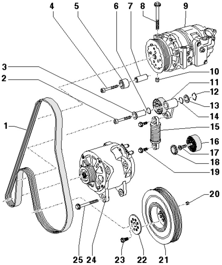
37.1a. Installation details of the auxiliary drive components of the BTR engine:
1 - Drive belt;
2 - Bolt, 50 Nm;
3 - Support sleeve;
4 - Bolt, 22 Nm;
5 - Right intermediate roller;
6, 14 - Sealing ring;
7 - Spacer sleeve;
8 - Compressor mounting bolt 9;
9 - Air conditioning compressor;
10 - Centering sleeve, 2 pcs.;
11 - Belt tensioner 1;
12 - Retainer, depends on the version;
13 - Washer;
15 - Tensioner spring;
16 - Left intermediate roller;
17 - Bolt, 25 Nm;
18 - Plug;
19 - Bolt, 22 Nm, tightened after installing belt 1;
20 - Centering sleeve in pulley 21;
21 - Crankshaft pulley, installed in only one position;
22 - Washer;
23 - Bolt, to be replaced, 30 Nm, then tighten to an angle of 45°;
24 - Generator;
25 - Generator mounting bolt.
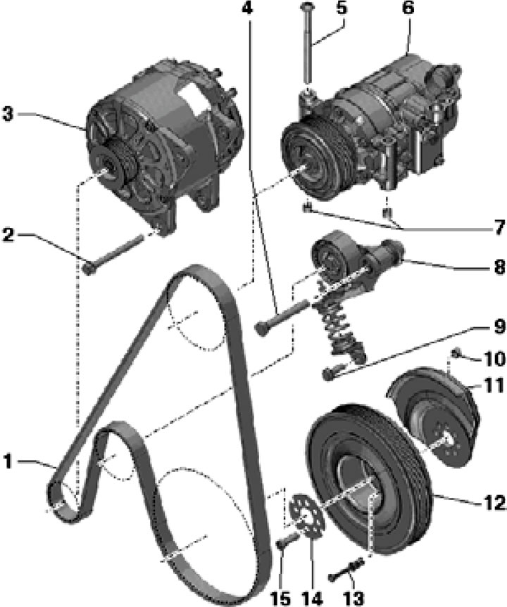
37.1b. Installation details of auxiliary drive components of CCFA/CCFC engines:
1 - Drive belt;
2 - Generator mounting bolt;
3 - Generator;
4 - Bolt, 50 Nm;
5 - Compressor mounting bolt 6;
6 - Air conditioning compressor;
7 - Centering sleeve, 2 pcs.;
8 - Belt tensioner 1;
9 - Bolt, 22 Nm, tightened after installing belt 1;
10 - Centering sleeve in damper 11;
11 - Torsional vibration damper, can be installed in only one position;
12 - Crankshaft pulley, installed in only one position;
13 - Transport lock for new assembly of parts 11 and 12;
14 - Washer;
15 - Bolt, to be replaced, 30 Nm, then tighten to an angle of 45°.
If the belt being removed is to be reinstalled, mark the direction of its movement first so that it can be reinstalled in the same manner.
Drive belt
2. Remove the top engine cover (see Section 19 of Chapter 1). On CCFA/CCFC engines, disconnect the connectors (1-3 in the illustration).
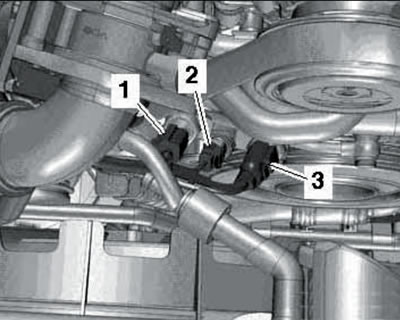
37.2. Connectors on the front side of CCFA/CCFC engines.
3. Loosen the belt tension. To do this on the BTR engine, turn the tensioner in the direction of the arrow (see illustration 37.3a) 3/8 inch square.
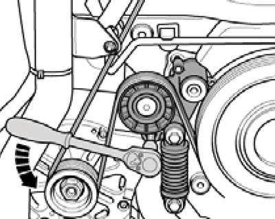
37.3a. Loosening the BTR engine drive belt tension.
On CCFA/CCFC engines, loosen the tensioner pulley bolt one turn (1 in illustration 37.3b), turn the tensioner counterclockwise and lock it with the T10060A tool.
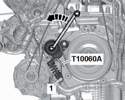
37.3b. Fixing the drive belt tensioner of CCFA/CCFC engines.
4. Remove the drive belt. On a BTR engine, release the tensioner.
5. Installation is carried out in reverse order. The generator and compressor mount fasteners must be tightened before installing the belt. Bolt (1 in illustration 37.3b) tightened after installing the belt. Make sure the belt is positioned correctly in the grooves. The belt routing diagram on the BTR engine is shown in the illustration; on CCFA/CCFC engines the rollers (3 and 5) are missing.
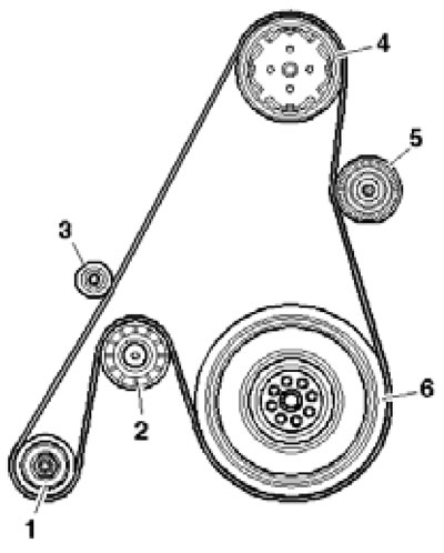
37.5. BTR engine drive belt routing diagram.
1 - Generator;
2 - Tensioner;
3, 5 - Intermediate roller;
4 - Air conditioning compressor;
6 - Crankshaft pulley.
If using a used belt, install it with the same side up (according to the marks made during removal).
Idler rollers and drive belt tensioner
6. Remove the drive belt.
7. To remove the intermediate rollers (bTR engine) just unscrew the bolts that secure them (4 and 17 in illustration 37.3a).
8. To remove the tensioner, unscrew the bolts (see illustration) or (2 and 19 in illustration 37.3a).
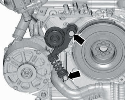
37.8. Drive belt tensioner mounting bolts on CCFA/CCFC engines.
Crankshaft pulley
9. Remove the drive belt (see above) and the front sound insulation panel under the engine compartment (see Section 19 of Chapter 1).
10. On the BTR engine, unscrew the bolts (23 in illustration 37.1a) and remove the pulley (21) with the washer (22).
11. On CCFA/CCFC engines, remove the bolts (15 in illustration 37.1b) and remove the pulley (12) with the washer (14), vibration damper (11) and bushing (10). If the pulley is being replaced, remove the retainer (13).
12. Installation is carried out in reverse order. Use a new washer and pulley mounting bolts. Due to the offset holes, the pulley can only be installed in one position.
This publication is borrowed from the resource: AUDIMANUAL.RU