
Table of contents: Cylinder head cover ↓ Removal/installing the left cylinder… ↓ Removal/installing the right… ↓
1. The details of installation of cylinder heads and their covers are shown on illustrations 11.1a-c using the right row of cylinders as an example.
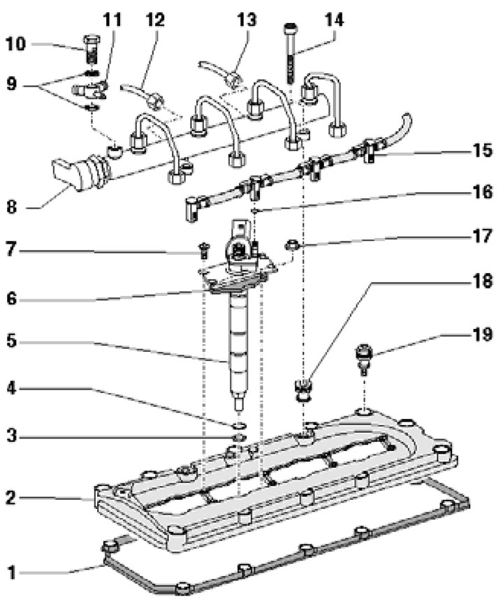
42.1a. BTR engine right cylinder head cover installation details:
1 - Cover gasket 2;
2 - Cylinder head cover;
3 - Copper seal, replaceable;
4, 9, 16 - Sealing rings, subject to replacement;
5 - Nozzle;
6 - Holder;
7, 14 - Bolt;
8 - Fuel distribution line with high-pressure pipes;
10 - Hollow bolt;
11 - Connecting node;
12 - High pressure pipe from the fuel injection pump;
13 - High pressure pipe from the fuel distribution line on another bank of cylinders;
15 - Return line;
17 - Nut;
18 - Bushing with seal;
19 - Bolt with seal, to be replaced, 8 Nm, then tighten to an angle of 90°.
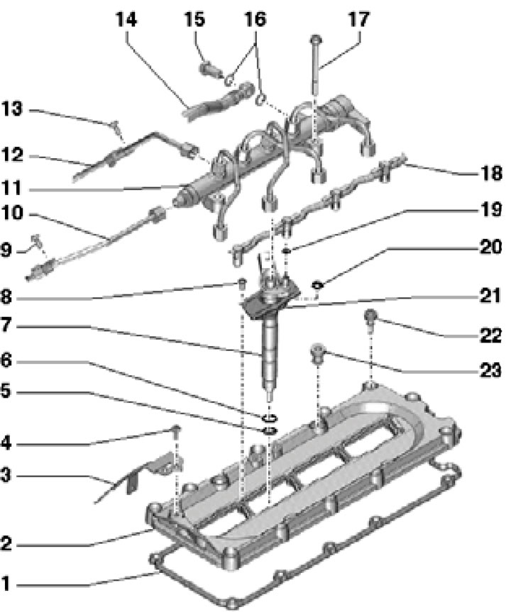
42.1b. Right cylinder head cover installation details for CCFA/CCFC engines:
1 - Cover gasket 2;
2 - Cylinder head cover;
3 - Bracket;
4 - Bolt, 5 Nm;
5 - Copper seal, must be replaced;
6, 16, 19 - Sealing rings, subject to replacement;
7 - Nozzle;
8, 9, 13, 17 - Bolt;
10 - High pressure pipe from the fuel injection pump;
11 - Fuel distribution line with high-pressure pipes;
12 - High pressure pipe from the fuel distribution line on another bank of cylinders;
14, 18 - Return line;
15 - Hollow bolt;
20 - Nut;
21 - Holder;
22 - Bolt with seal, to be replaced, 8 Nm, then tighten to an angle of 90°;
23 - Bushing with seal.
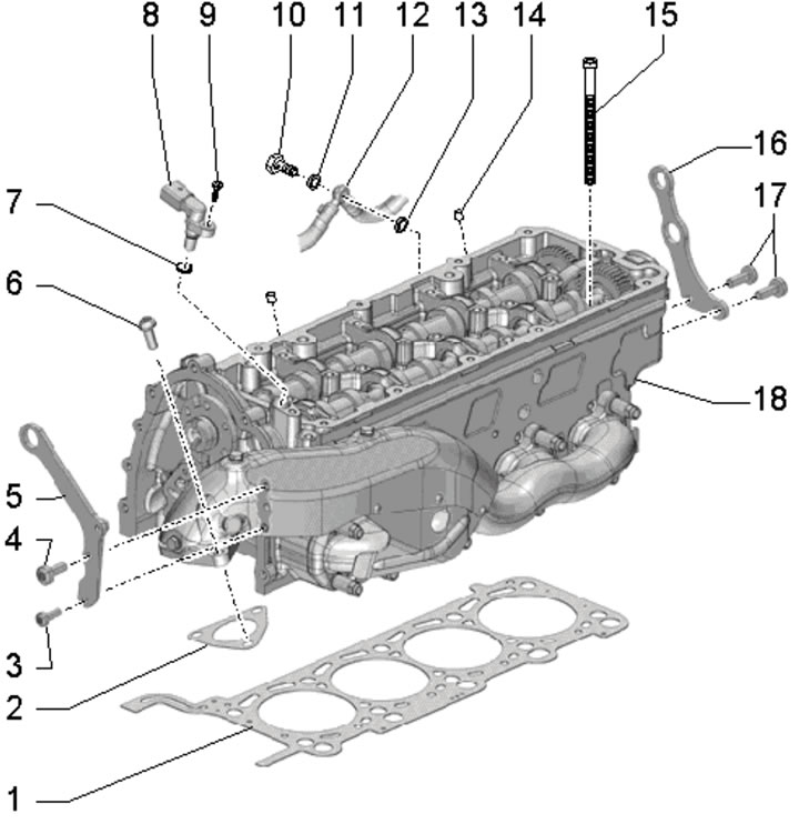
42.1s. Right cylinder head installation details:
1 - Cylinder head gasket, part number must face the cylinder head;
2 - Gasket, subject to replacement;
3, 9 - Bolt, 9 Nm;
4, 17 - Bolt, 23 Nm;
5 - Rear engine lifting eye;
6 - Bolts;
7, 11, 13 - O-ring, subject to replacement;
8 - CMR sensor;
10 - Hollow bolt, 12 Nm;
14 - Centering bushings for intake manifold, 2 pcs.;
15 - Bolt to be replaced: 35 Nm, then 60 Nm, then tighten twice to an angle of 90°;
16 - Front engine lifting eye;
18 - Cylinder head.
Cylinder head cover
2. Remove the injectors of the corresponding cylinder bank (see Chapter 4).
3. When working on the left bank of cylinders, release the fuel hoses in the direction of the arrows (A and B in the illustration), unscrew the bolt (1) and remove the bracket (2).

42.3. Removing the fuel hose bracket on the left bank of cylinders.
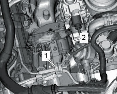
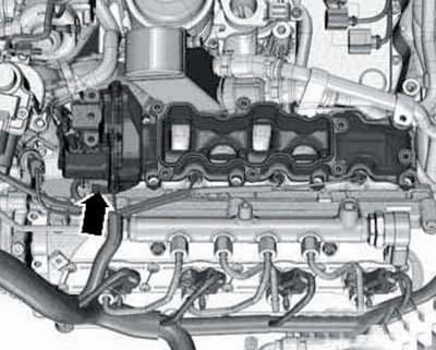
4. When working on the right row of cylinders, move away from the bracket (1 in illustration 42.4a) electrical wiring, unscrew the bolt (arrow) and remove the bracket.
42.4a. Bracket mounting bolt.
Then disconnect the connector (2 in illustration 42.4b), loosen the bolt (1 in illustration 36.15), unscrew the bolt (2) with the nut and move the rear right coolant pipe to the side.
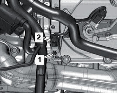
42.4b. Connector (2) and bolt (1) for fastening the sensor.
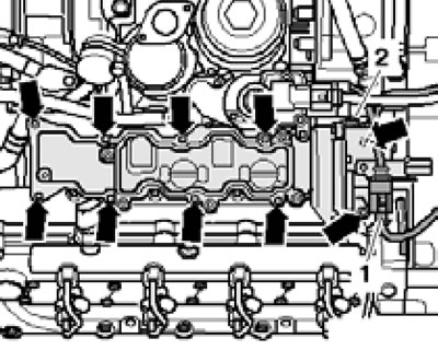
5. Loosen the cover mounting bolts in a diagonal order (see illustration), then completely unscrew them and remove the lid.
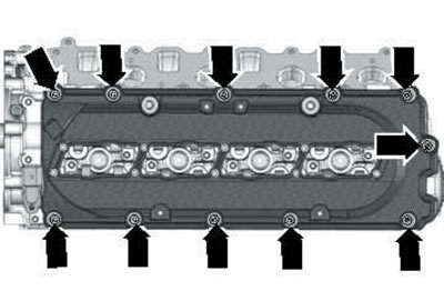
42.5. Cylinder head cover fastening bolts.
6. Installation is carried out in reverse order. Before installation, the mating surfaces of the cylinder head and its cover must be clean and degreased. Use a new cylinder head cover gasket.
Tighten the cover mounting bolts diagonally, first with a force of 8 Nm, and then tighten them to an angle of 90°.
Removal/installing the left cylinder head
7. Drain the coolant (see Chapter 3).
8. Remove the timing chain from the camshaft of the corresponding cylinder head (see Section 40).
9. Remove the upper section of the intake manifold (see Chapter 4).
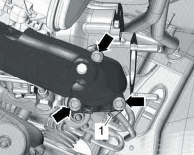
10. On CCFA/CCFC engines, remove the fuel injection pump (see Chapter 4), unscrew the bolts (see illustration) and remove the fuel injection pump bracket.
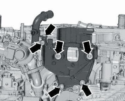
42.10. Fuel injection pump bracket mounting bolts.
11. Disconnect the coolant hoses (arrows in the illustration) from the left EGR connection unit, unscrew the bolts (3).
42.11. Clamps (arrows) and bolts (3) of the left EGR connection unit.
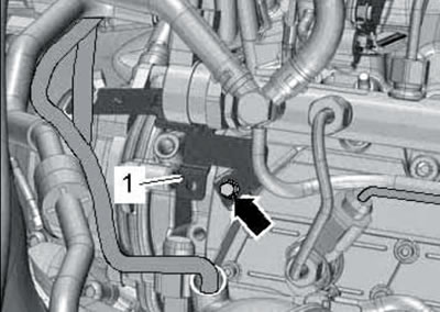
12. On CCFA/CCFC engines, remove the non-return valve from the holder (1 in the illustration) and disconnect the connector (2) of the "V275" actuator of the intake manifold valve No. 2.
42.12. Non-return valve (1) and electrical wiring connector (2) of CCFA/CCFC engines.
13. On the BTR engine, remove the non-return valve from the holder, remove the electrical wiring connector from the holder (1 in the illustration) Fuel injection pump and disconnect the connector (2) of the "V275" activator of valve No. 2 of the intake manifold.
42.13. Connectors of the fuel injection pump (1) and the "V275" activator (2) of the BTR engine.
14. Unscrew the bolt (1 in illustration 35.17) refrigerant line holder.
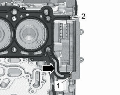
15. Disconnect the glow plug wiring connectors (see Chapter 5), remove the cylinder head cover (see subsection above) and unscrew the hollow bolt (see illustration) coolant pipes on the corresponding cylinder head.
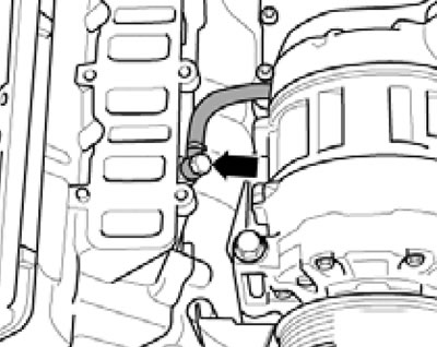
42.15. Hollow bolt of coolant pipe on cylinder head.
16. Remove the upper bolts (arrows in the illustration) turbocharger on the corresponding side.
42.16. Turbocharger upper bolts.
17. Loosen the cylinder head mounting bolts in the following sequence: (1-10 in the illustration), then completely unscrew them and carefully remove the cylinder head.
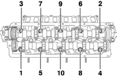
42.17. Sequence of unscrewing cylinder head bolts.
Place it so as not to damage the glow plugs.
18. Please take note of the comments listed in paragraph 20 of Section 11.
19. Set the crankshaft and camshafts to TDC and lock them as described in paragraphs 5-6 of Section 40.
20. Pay attention to the number of holes (1 in the illustration) and the part number (2) on the gasket.
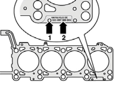
42.20. Cylinder head gasket identification.
The left and right cylinder head gaskets are different from each other. If the cylinder head or its gasket needs to be replaced, select a new gasket with the same number of holes as the old gasket. If the connecting rod and piston group parts have been replaced, it will be necessary to select a new gasket based on the piston protrusion at TDC (see Section 14).
21. Clean the mating surfaces from oil and grease. For further actions after applying the sealant, the relevant parts should be installed within 15 minutes.
22. Apply beads of sealant no more than 4.0 mm thick to the joints of the cylinder block and the lower timing chain cover (see illustration).
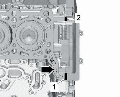
42.22. Sealant at the joints of the cylinder block and the lower timing chain cover.
Note: On the right cylinder head, the sealant must not enter the oil channel (arrow).
23. Install the cylinder head gasket onto the centering bushings on the cylinder block and fill the cutouts with sealant (1 and 2 in the illustration) gaskets.
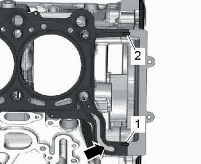
42.23. Grooves in the cylinder head gasket.
Note: On the right cylinder head, the sealant must not enter the oil channel (arrow).
24. Apply beads of sealant no more than 4.0 mm thick perpendicular to the ends of the cylinder head gasket (see illustration).
42.24. Places of sealant application.
Note: On the right cylinder head, the sealant must not enter the oil channel (arrow).
25. Place the cylinder head and tighten the new bolts by hand. Tighten the cylinder head bolts in sequence (10-1 in illustration 42.17): with a force of 35 Nm, then with a force of 60 Nm, and then tighten twice to an angle of 90°.
Note: After this, tightening the bolts is not allowed.
26. Install the remaining parts in the reverse order of their removal.
Removal/installing the right cylinder head
27. Follow the steps described in paragraphs 7-9.
28. On CCFA/CCFC engines, remove the right coolant pipes intended for the EGR system (see Chapter 4).
29. Disconnect the connector (1 in the illustration) activator "V338" EGR.
42.29. Connector (1) of the "V338" EGR activator.
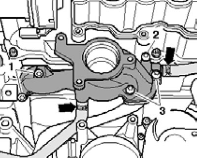
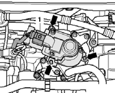
30. On the BTR engine, unscrew the bolt (4 in the illustration) and separate the cooling system flange.
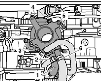
42.30. Connections and fasteners of the connecting unit with the "V338" EGR activator (bTR engine).
Disconnect the coolant hoses (2 and 6), unscrew the bolts (1, 3 and 5) and separate the connecting unit with the right EGR activator "V338".
31. On CCFA/CCFC engines, disconnect the connector (2 in the illustration), disconnect the coolant hoses (3 and 6), unscrew the bolts (1 and 5) and separate the connecting unit with the right activator "V338" EGR.
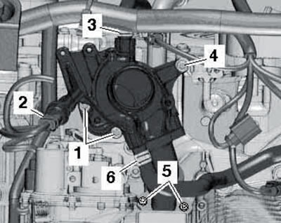
42.31. Connections and fasteners of the connecting unit with the "V338" EGR activator (cCFA/CCFC engines).
32. Disconnect the connector of the "V157" actuator of the intake manifold flap (see illustration).
42.32. Activator connector "V157".
33. Follow the steps described in paragraphs 15-26.