
Note: Please note the notes at the beginning Section 14.
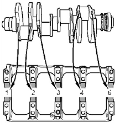
1. The crankshaft installation details are shown in the illustration.
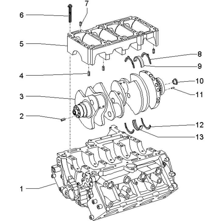
45.1. Crankshaft installation details:
1 - Cylinder block, run-in to bed 5;
2 - Centering sleeve for crankshaft pulley;
3 - Crankshaft;
4 - Centering bushings of bed 5 (see illustration 45.2);
5 - Shaft bed 3, run-in to the cylinder block;
6 - Bed mounting bolt 5 (see illustration 45.3), subject to replacement;
7 - Oil pump centering sleeves, 2 pcs.;
8, 12 - Thrust washers, installed only on bearing #4, oil grooves facing outward;
9 - Lower main bearing shell (in bed 5), without oil groove;
10 - Centering sleeve of the torque converter, at the rear end of shaft 3;
11 - The centering pin of the drive disk must fit tightly in shaft 3;
13 - Upper main bearing shell (in the cylinder block), with oil groove.
2. Depending on the design, two or three centering bushings must be installed in the crankshaft bed (1-3 in the illustration).
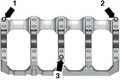
45.2. Centering bushings in the crankshaft bed.
The bushing (3) is not always installed.
3. After removing the crankshaft bed, use new bolts to secure it. Tighten the bed mounting bolts in sequence (1-20 in the illustration) in three approaches: first with a force of 30 Nm, then with a force of 50 Nm, and finally pull to an angle of 90°.
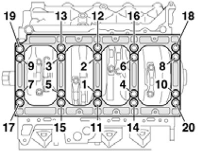
45.3. Sequence of tightening the crankshaft bed fasteners.
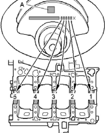
4. The main bearing shells are marked by thickness with colored dots. The inserts of the required thickness are installed at the factory. Liners worn down to the nickel layer should be replaced. You can determine which color dotted bearing to use by the letters: G - yellow, B - blue, R - red. The letters for selecting the upper bearings are located on the cylinder block, next to the corresponding bearing (see illustration 44.4a), and the letters for selecting the lower liners are located on the crankshaft (see illustrations 44.4bd).
45.4a. Letters for selecting upper main bearing shells.
45.4b. Letters or colored dots for selecting lower main bearing shells (option 1: on separate cheeks of the crankshaft).
45.4s. Letters for selecting lower main bearing shells (option 2: on the front cheek of the crankshaft).
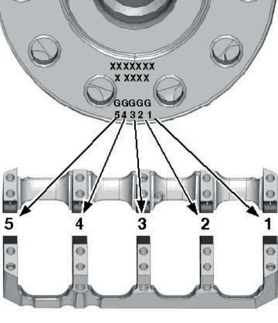
45.4d. Letters for selecting lower main bearing shells (option 3: on the front flange of the crankshaft).
Instead of letters for selecting lower liners, colored dots can be applied directly. In some cases, the color markings for selecting the lower main bearing shells may not be visible. Then you should measure the diameter of the corresponding main journal and select a bearing with the corresponding color mark:
- 64.978-64.972 mm - red,
- 64.972-64.965 mm - yellow,
- 64.965-64.958 mm - blue.
5. The parts of the connecting rod and piston group are shown in the illustration. Liners worn down to the nickel layer should be replaced.
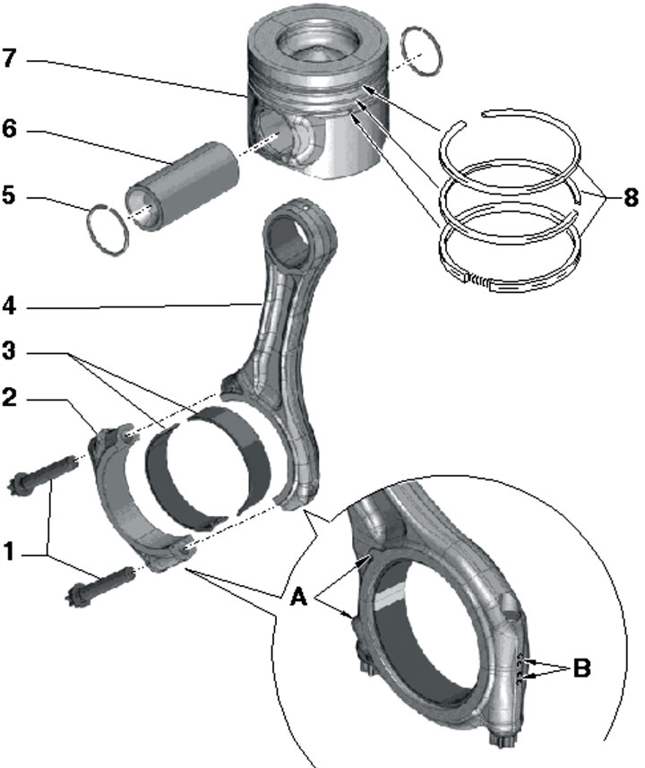
45.5. Connecting rod and piston group parts:
1 - Cover fastening bolts 2, subject to replacement, tighten with lubricated threads and mating surface: 50 Nm, then tighten to an angle of 90°;
2 - Connecting rod bearing cap, installed only in one position and only on a pair of connecting rods; with the mark "B" indicating belonging to the cylinder and the protrusion "A" on the timing drive side;
3 - Connecting rod bearing shells;
4 - Connecting rod with mark "B" and protrusion "A" (see point 2), can only be replaced as a complete assembly with cover 2;
5 - Retaining ring, 2 pcs., subject to replacement;
6 - Piston pin, to facilitate removal, heat the piston to 60°C;
7 - Piston, arrow should point towards the crankshaft pulley;
8 - Piston rings are installed at 120° intervals between locks, the "TOP" mark should face the piston bottom.
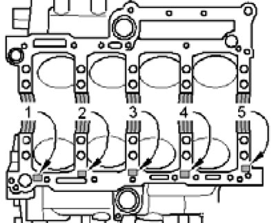
6. Oil nozzles (2 in the illustration) to cool the pistons, they are fastened with bolts (1) with a force of 9 Nm.
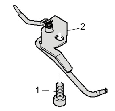
45.6. Bolt (1) for fastening the oil nozzle (2) for cooling the piston.
7. The wider areas on the connecting rod bearing caps should face the nearest main bearing (by analogy with illustration 14.6).
8. When installing new parts of the connecting rod and piston group or a "short" cylinder block, a new cylinder head gasket should be selected (separately for each head). The thickness of the gasket is determined based on the maximum protrusion of any of the pistons in a given cylinder bank when that piston is at TDC. Depending on the maximum protrusion of the pistons, a gasket with one, two, or three holes is used (1 in illustration 42.20), see Specifications.
9. The connecting rod bearing shells are marked by thickness with colored dots and are installed only in the following pairs (see table):
| Couple type | 1 | 2 | 3 |
| Connecting rod bearing | yellow | blue | red |
| Insert in the connecting rod bearing cap | yellow | red | blue |
The original material is located on the website: AUDImanual.ru