
Table of contents: Removal and installation camshafts ↓ Checking hydraulic compensators ↓ Replacing valve stem seals ↓
Caution: After installing the camshafts, wait at least 30 minutes before starting the engine to allow the hydraulic lifters to settle. Otherwise, the valves may hit the pistons.
1. The installation details of the timing components are shown in the illustration using the example of the left cylinder head.
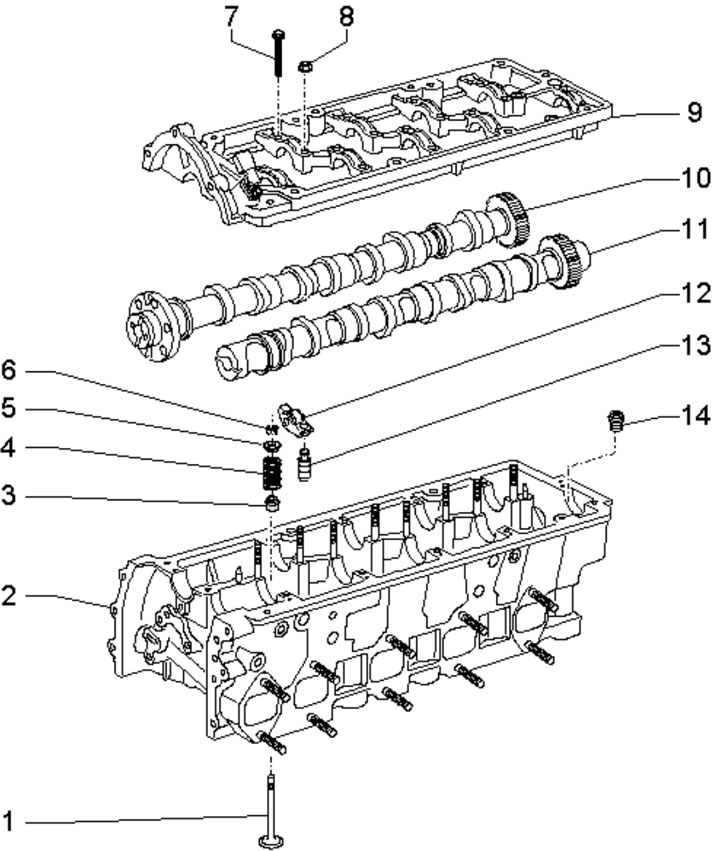
43.1. Timing belt component installation details (left cylinder head):
1 - Valve, sodium filled;
2 - Cylinder head;
3 - Oil deflector cap;
4 - Valve spring;
5 - Spring plate 4;
6 - Split valve lock crackers;
7/8 - Bed mounting bolt/nut 9, 10 Nm;
9 - Camshaft bed, with built-in bearings;
10/11 - Intake/outlet camshaft;
12 - Rocker arm;
13 - Hydraulic valve clearance compensator;
14 - Not used (pressure relief valve).
2. Processing of valves and their seats, except for lapping, is not permitted.
3. When working with the timing belt, arrange the removed parts as follows. so that they can then be installed in their original places.
Removal and installation camshafts
Note: The left cylinder head camshaft bed cannot be removed with the engine installed, so the engine must first be removed (see Section 35) and the left exhaust manifold (see Chapter 4).
Note: Special tools are required to install the camshafts.
4. Remove the upper timing chain from the shafts of the corresponding cylinder head (see Section 40).
5. Remove the corresponding cylinder head cover (see Section 42).
6. Remove the rear engine lifting eye.
7. Loosen the bolts and nuts in sequence (22-1 in the illustration).
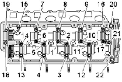
43.7. Sequence of tightening the camshaft bed fasteners.
Remove the fasteners completely and carefully remove the bed (it is held in place by sealant). Remove the camshafts, being careful not to damage the rocker arms and hydraulic lifters. If necessary, remove the rocker arms and hydraulic lifters.
8. Make sure that the axle bearings in the shaft bed are not damaged.
9. Seal the holes to prevent dirt from entering the lubrication system and remove any remaining sealant from the cylinder head and shaft bed. Use a plastic drill brush attachment. Clean mating surfaces from oil and grease. Lubricate the working surfaces of both camshafts.
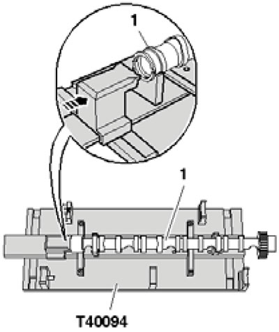
10. When working on the left cylinder head, assemble the T40094 tool by inserting the support -/1 into position "G" and the support -/2 into position "A" (see illustration 12.17). Place the exhaust shaft (1 in illustration 43.10a) into the T40094/1 and -/2 supports and turn it so that it can be locked at TDC with the locking device (arrow).
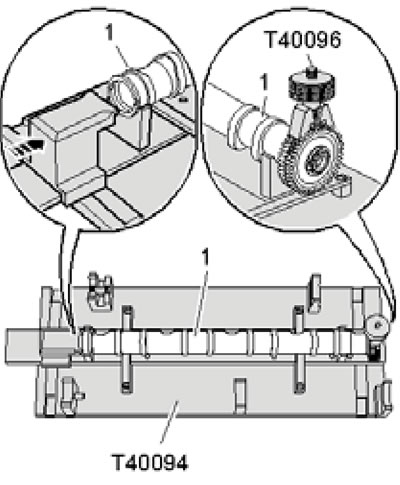
43.10a. Fastening the left exhaust shaft in the T40094 device.
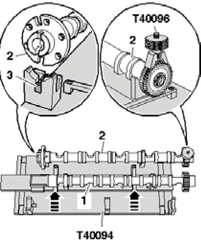
Install the T40096 device onto the shaft teeth so that the two levers of this device sit on the two halves of the gear (one lever for each half). Secure the T40096 tool with a knurled bolt so that the tooth surfaces are aligned. Lay the intake shaft (2 in illustration 43.10b) into the T40094 fixture, aligning the centering pin (3) with the cutout.
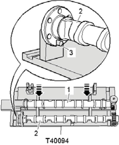
43.10b. Fastening the left intake shaft in the T40094 device.
Move the exhaust shaft (1) towards the intake shaft in the direction of the arrows until the gears engage.
11. When working on the right cylinder head, assemble the T40094 tool by inserting the support -/1 into position "E" and the support -/2 into position "B" (see illustration 12.17). Place the exhaust shaft (1 in illustration 43.11a) into the T40094/1 and -/2 supports and turn it so that it can be locked at TDC with the locking device (arrow).
43.11a. Fastening the right exhaust shaft in the T40094 device.
Lay the intake shaft (2 in illustration 43.11b) into the T40094 fixture, aligning the centering pin (3) with the cutout.
43.11b. Fastening the right intake shaft in the T40094 device.
Install the T40096 tool onto the teeth of the intake shaft so that the two arms of this tool sit on the two halves of the gear (one lever for each half). Secure the T40096 tool with a knurled bolt so that the tooth surfaces are aligned. Move the exhaust shaft (1) towards the intake shaft in the direction of the arrows until the gears engage.
12. Install the camshafts on their bearings (1 in the illustration).
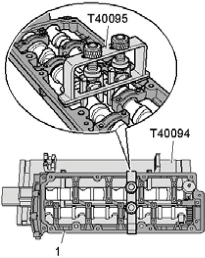
43.12. Installing the bed on the camshafts.
All bearings must fit onto the shafts. Install the T40095 fixture on the shafts (align the bracket arms as required and tighten the knurled nuts).
13. Turn the camshaft bed over and apply a bead of sealant to its clean mating surface as shown in the illustration.
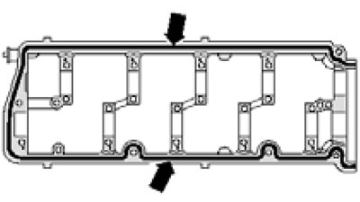
43.13. Sealant application diagram.
The sealant should completely fill the groove and protrude 1.5-2.0 mm. After applying the sealant, the bed should be installed within 5 minutes.
Note: For clarity, the bed is shown without camshafts.
14. Make sure all rocker arms are in contact with the valves and hydraulic lifters. Install the bed together with the shafts and devices T40095 and -96 on the cylinder head and tighten the bolts/nuts in the sequence (1-22 in illustration 43.7). Tighten the fasteners by hand first, so that the bed is in full contact with the cylinder head. After this, tighten the fasteners to 10 Nm.
15. Remove tools T40095 and -96, replace the camshaft oil seal (see the relevant subsection above) and install the remaining parts.
Checking hydraulic compensators
Note: Maintenance of hydraulic compensators is not provided. Valve noise immediately after starting the engine does not indicate a malfunction.
16. Start the engine and wait until the coolant temperature rises to approximately 80°C. Increase the engine speed to 2500 rpm for approximately 2 minutes. If necessary, take a test drive.
17. If the hydraulic lifters continue to make noise after this, determine which of them are faulty as described below.
18. Remove the corresponding cylinder head cover (see Section 42) and the front soundproofing panel under the engine compartment (see section 19 of Chapter 1).
19. Insert the guide pin with a smaller diameter (2 in illustration 4.73a) into the T40058 adapter. Using this adapter, turn the crankshaft clockwise (see illustration 35.55), so that the cam for the hydraulic compensator being tested is facing upwards.
20. Press the rocker arm (see illustration 12.44) and determine the gap between the cam and the hydraulic compensator: if it is possible to insert a 0.20 mm thick feeler gauge into this gap, replace the hydraulic compensator (see the subsection "Removing and installing camshafts" above).
21. After checking, install the cylinder head cover.
Replacing valve stem seals
22. Replacing the valve stem seals is done in the same way as on 1st generation 3.0 TDI engines (see Section 12).
(The original article is available on the website: audimanual.ru)