
Warnings
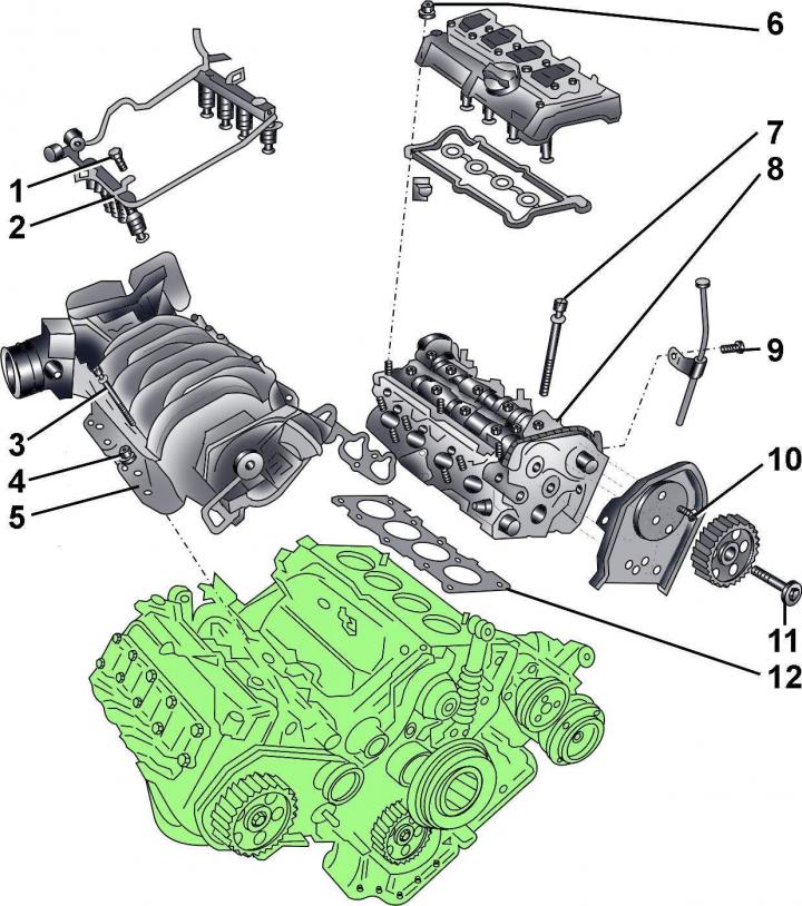
Fig. 3.2–32. Cylinder head: 1 – bolt, 10 Nm; 2 – fuel distributor; 3 – bolt, 20 Nm; 4 – bolt, 20 Nm; 5 – intake manifold; 6 – nut, 10 Nm; 7 – cylinder head mounting bolt; 8 – cylinder head; 9 – bolt, 10 Nm; 10 – bolt, 10 Nm;
11 – bolt, 55 Nm; 12 – cylinder head gasket
When installing the cylinder head with a gasket, it is necessary to use new bolts 7 (Fig. 3.2–32) for fastening the head.
When replacing the cylinder head, it is necessary to fill the cooling system with fresh coolant.
All clamps and collars that are damaged or cut during engine removal must be replaced with new ones when installing the cylinder head.
Before disconnecting the battery, find out if you have a radio activation code.
Removal
Remove the cylinder head on a cold engine.
The battery is located under the luggage compartment floor.
Turn off the ignition and disconnect the ground wire from the battery.
Drain the coolant from the engine cooling system.
Remove the left exhaust pipe.
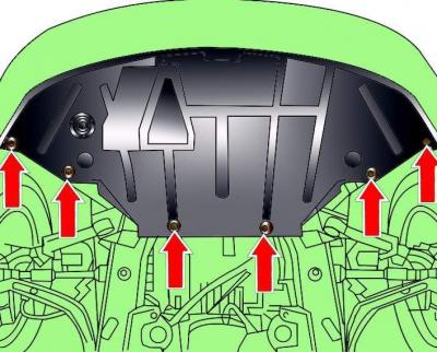
Fig. 3.2–2. Location of the engine compartment lower mudguard mounting screws
Remove the lower engine compartment splash guard (see Fig. 3.2–2).
Unscrew the left and right exhaust pipes.
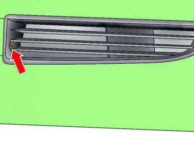
Fig. 3.2–1. Location of the screw securing the left ventilation grille
Loosen the screw securing the left bumper ventilation grille (at the same time the right grid is also freed) and remove the grates (see Fig. 3.2–1).
Remove the timing belt.
Remove the vacuum hose from the cruise control unit.
Remove the accelerator cable.
Disconnect the coolant hose from the coolant drain valve.
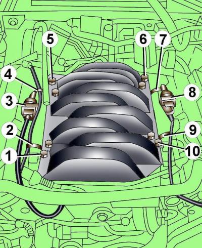
Fig. 3.2–5. Location of electrical connectors and fuel line fastening elements: 1, 5, 6, 10 – fuel line fastening bolts; 2, 4, 7, 9 – clamps; 3, 8 – electrical connectors of knock sensors
Disconnect electrical connectors 3 and 8 from the knock sensors on the left and right sides of the fuel line (see Fig. 3.2–5).
Release the four clamps securing electrical wires 2, 4, 7 and 9.
Disconnect the electrical connectors from the fuel injectors on the left and right sides of the engine.
Remove bolts 1, 5, 6 and 10 and carefully remove the fuel line.
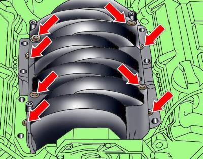
Fig. 3.2–33. Location of intake manifold mounting bolts
Loosen the bolts and remove the intake manifold (Fig. 3.2–33).
Remove the front bolts securing the left and right exhaust manifolds.
Disconnect the electrical connectors from the ignition coils.
Unscrew and remove the cooling system pipe located between the heads at the rear of the engine.
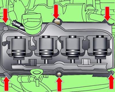
Fig. 3.2–34. Location of cylinder head cover mounting bolts
Remove the cylinder head covers (Fig. 3.2–34).
On the left cylinder head, unscrew and remove the guide tube for the engine oil level indicator (dipstick).
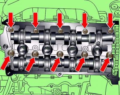
Fig. 3.2–35. Location of cylinder head mounting bolts
Gradually loosen and then completely remove the cylinder head mounting bolts (Fig. 3.2–35).
Remove the cylinder head and place it on a soft surface.
Preparing the head for installation
The mating surfaces of the cylinder head and block must be completely clean. Use a hard plastic or wooden scraper to clean them. Be careful when cleaning, as the aluminum alloy is very easy to damage. Make sure that carbon deposits do not get into the oil and water channels. This is especially important for the lubrication system, as carbon deposits can block the supply of oil to engine parts. Clean the channels if necessary.
Check the mating surfaces of the cylinder head and block for nicks, deep scratches and other damage. Minor defects can be eliminated by mechanical treatment; in case of significant defects, replace the parts.
Using a metal ruler and feeler gauge, check the flatness of the mating surfaces.
If the deviation from flatness exceeds 0.1 mm, it is necessary to regrind the head. Cylinder head height a after mechanical processing must be at least 139.25 mm (Fig. 3.2–36).
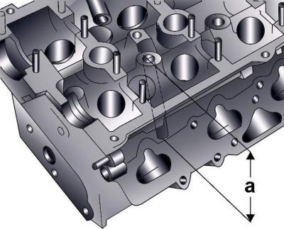
Fig. 3.2–36. Cylinder head height measurement location
Clean the bolt holes in the block. When screwing a bolt into an oil-filled hole, the block may burst due to hydraulic pressure.
Installation
Installation is carried out in the reverse order of removal, taking into account the following.
Replace the cylinder head bolts.
The new cylinder head gasket must be removed from the packaging immediately prior to installation.
Place the gasket on the guide pins with the "oben" or "top" lettering facing the head.
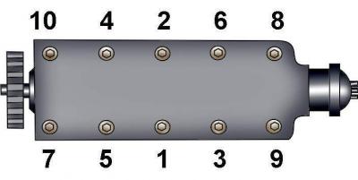
Fig. 3.2–37. Cylinder head bolt tightening sequence
Insert the cylinder head mounting bolts and tighten them by hand, then in the sequence shown in Figure 3.2–37 in three stages:
- 1st - torque 40 Nm;
- 2nd - torque 60 Nm;
- 3rd - turn it by 180°.
Further tightening of the cylinder head mounting bolts is not required.
Before installing the intake manifold, connect the front crankcase ventilation hose.
Before installing the cylinder head cover in place, lubricate the cover gasket on both sides with a thin layer of silicone grease D 007 000 04.
Using a thin screwdriver blade, apply a layer of silicone grease D 007 000 04 to the transitions of the edges near the front and rear camshaft covers (Fig. 3.2–38).
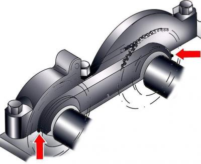
Fig. 3.2–38. Application areas of silicone grease D 007 000 04 on the transitions of edges near the rear camshaft covers