
Table of contents: Removal ↓ Exhaust camshaft ↓ Intake camshaft ↓ Installation ↓ Intake camshaft ↓ Exhaust camshaft ↓ Checking hydraulic valve lifters ↓ Valve seat machining ↓ Replacing camshaft sealing rings ↓ Warning ↓ Checking and adjusting the alignment… ↓
Removal
Remove the timing belt.
Remove the cylinder head cover.
Remove the camshaft pulley.
Exhaust camshaft
Unscrew the flange and the distributor bearing cover.
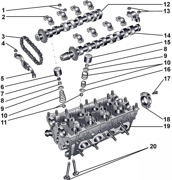
Fig. 3.2–39. Valve mechanism: 1 – nuts, 15 Nm; 2 – camshaft bearing cap; 3 – chain; 4 – nut, 15 Nm; 5 – Front camshaft bearing cover; 6 – hydraulic valve lifters; 7 – compensating element; 8 – valve crackers; 9 – upper valve spring plate; 10 – valve springs; 11 – oil deflector caps; 12 – intake camshaft; 13 – nuts, 15 Nm; 14 – exhaust camshaft; 15 – hydraulic valve lifters; 16 – lower valve spring plate; 17 – bolt, 10 Nm; 18 – flange; 19 – cylinder head; 20 – valves
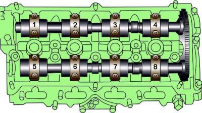
Fig. 3.2–40. Location and numbering of camshaft bearing caps
Unscrew and remove the camshaft bearing caps on the chain side and covers 2 and 3 (Fig. 3.2–40).
Gradually, evenly and crosswise, unscrew the camshaft bearing caps 1 and 4.
Intake camshaft
Unscrew and remove camshaft bearing caps 6 and 7.
Gradually, evenly and crosswise, unscrew the camshaft bearing caps 5 and 8.
Remove the camshafts.
Installation
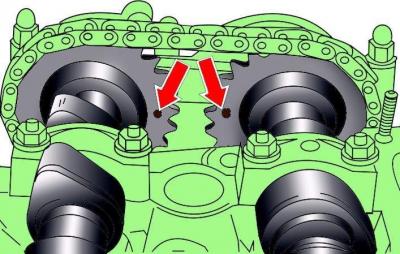
Fig. 3.2–41. Installing the intake camshafts
Lubricate the camshafts with a thin layer of engine oil and install them in the cylinder head so that the marks on the shaft sprockets are facing each other (Fig. 3.2–41).
When installing, keep in mind that the bearing caps are numbered from the front of the intake camshaft.
Before installing the outer camshaft covers, apply a thin layer of sealant D 454 300 02 to the mating surfaces of the covers.
Intake camshaft
Install covers 5 and 8 (see Fig. 3.2–40) of the camshaft bearings and secure them with nuts, tightening them gradually crosswise.
Exhaust camshaft
Install covers 1 and 4 (see Fig. 3.2–40) of the camshaft bearings and secure them with nuts, tightening them gradually crosswise.
Install and secure the remaining covers.
Further installation is carried out in the reverse order of removal.
Checking hydraulic valve lifters
Correct valve clearances have a major impact on engine performance. If the valve clearances are too large, the engine will become noisy and less efficient because the valves will open too late and close too early. If the valve clearances are too small, the valves will not close completely when the engine is hot, which can cause serious engine damage.
The engines are equipped with hydraulic tappets, which automatically compensate for the gap between the camshaft cam and the corresponding valve stem under the action of pressure in the lubrication system. Therefore, regular checking and adjustment of valve clearances is not required during operation. However, it is necessary to use motor oil good quality and recommended viscosity and replace it at the required intervals. When starting a cold engine, there is a slight delay in equalizing the engine oil pressure in all parts of the engine, especially in the hydraulic tappets. The valves may knock for about 10 seconds, after which they continue to operate silently.
If the engine has not been started for several days, the valves may knock for a longer period of time, as almost all the oil drains from the top of the engine and the bearing surfaces. During this time, care must be taken to avoid engine damage: avoid sudden changes in engine speed until all tappets are filled with engine oil. When warming up the engine, the fast idle speed (2000 to 2500 min⁻¹) should not be increased for 2 minutes or until the valves stop knocking. If the tappet noise does not stop, stop the engine and perform the following steps, with the engine temperature at least 80°C.
Remove the cylinder head cover.
While turning the crankshaft, position the cam straight up over the tappet being tested.
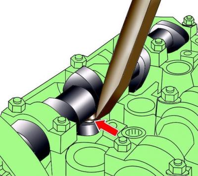
Fig. 3.2–42. Checking the free travel of the push rod
Press the plunger with a wooden or plastic wedge (Fig. 3.2–42). If the plunger free play is more than 0.2 mm, the plungers must be replaced.
Install the cylinder head cover.
Wait approximately 30 minutes before starting the engine. This is necessary to stabilize the hydraulic tappets, otherwise the pistons will hit the valves.
Valve seat machining
Valve seats with signs of wear or burning must be processed with the mandatory preservation of the angles and chamfer size.
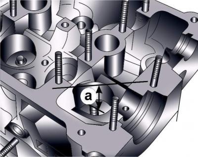
Fig. 3.2–43. Minimum permissible distance from the end of the valve to the upper surface of the cylinder head
If the valve seat must be machined, determine the maximum amount of metal that can be removed. Removing too much metal will impair the operation of the hydraulic tappets. Insert the valve into the guide bushing and press it against the valve seat. Measure the distance from the end of the valve stem to the top surface of the cylinder head (Fig. 3.2–43).
If the valve seat is excessively worn, machining is not allowed and the cylinder head must be replaced.
After processing the valve seats, they must be lapped.
Replacing camshaft sealing rings
Remove the timing belt.
Remove the camshaft pulleys on the left and right cylinder heads.
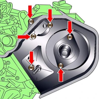
Fig. 3.2–44. Location of timing belt cover mounting bolts
Remove the timing belt covers on the left and right cylinder heads (Fig. 3.2–44).
Warning
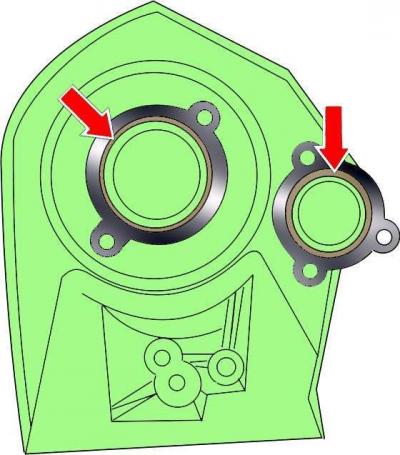
Fig. 3.2–46. Location of sealing rings in the front part of the cylinder head
On the left side there are two sealing rings and a camshaft sealing ring, on the right side there is one sealing ring and a camshaft sealing ring (see Fig. 3.2–46)
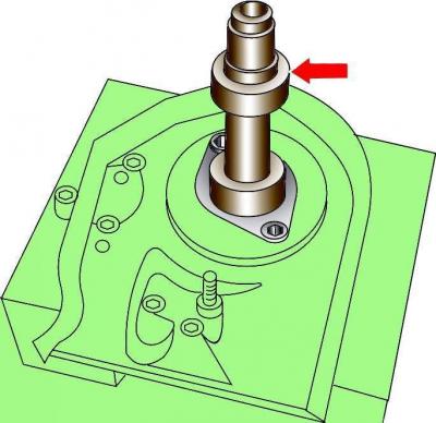
Fig. 3.2–45. Using special tool 2056 to remove the camshaft seal ring
Using special tool 2056, remove the camshaft seal ring (Fig. 3.2–45).
Warning: If even one sealing ring is damaged, the sealing rings on both sides must be replaced.
Clean the installation area of the sealing rings.
Lubricate the sealing lip and outer surface of the new O-ring with engine oil before installing it in place.
Using a drift, install the sealing ring into place.
Install the camshaft pulleys.
Install the timing belt.
Checking and adjusting the alignment of the poly V-belt
The alignment of the poly V-belt is checked between the air conditioning compressor and the power steering pump.
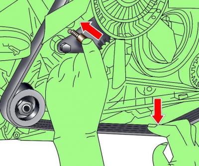
Fig. 3.2–10. Installing tool 3204 to loosen the poly V-belt tension
Loosen the tension of the poly V-belt by pressing on the lower branch of the poly V-belt and, using device 3204, fix the belt tensioner in this position (see Fig. 3.2–10). Remove the poly V-belt.
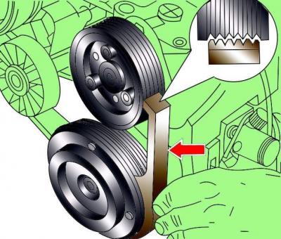
Fig. 3.2–47. Using the 3201 tool to check the groove alignment on the A/C compressor and power steering pump pulleys
Using tool 3201, check the alignment of the belt grooves on the A/C compressor and power steering pump pulleys (Fig. 3.2–47).
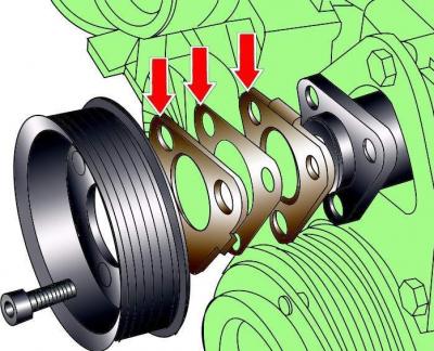
Fig. 3.2–48. Using shims to adjust the position of the power steering pump pulley
If the grooves on the pulleys do not match, unscrew the power steering pump pulley. Adjust the pulley position using 0.5 mm thick shims; 1.0 and 1.5 mm, which are supplied as spare parts (Fig. 3.2–48).
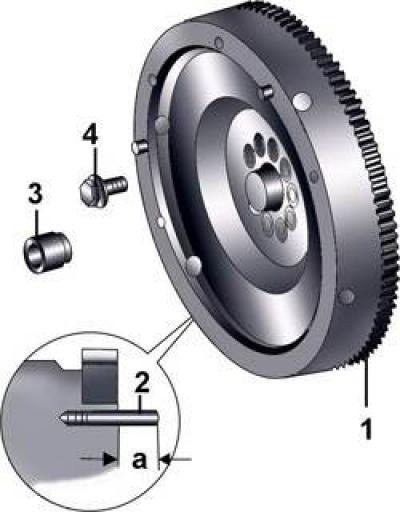
Fig. 3.2–49. Flywheel: 1 – toothed ring (before installation on the flywheel, it must be heated to a temperature of 200°C); 2 – pin for TDC sensor; 3 – needle bearing bushing; 4 – bolt