

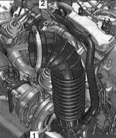
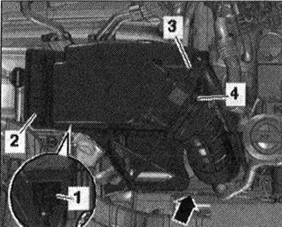
Disconnect the crankcase ventilation hose -2- by pressing the release buttons. Remove the air duct hose by loosening the hose clamp -1-.
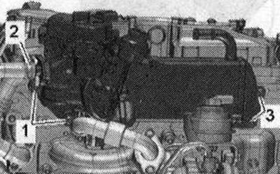
Remove bolts -1 and -3- from the exhaust gas recirculation radiator. -Pos. 2- do not take into account. Remove the timing belt from the camshaft timing belt pulley and the high pressure pump timing belt pulley. Remove the cylinder head cover.
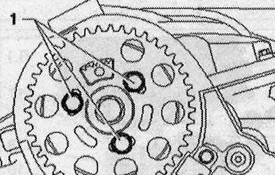
Unscrew bolts -1- and remove camshaft timing belt gear.
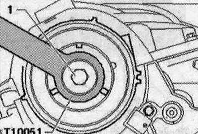
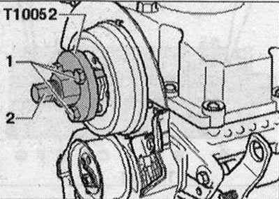
Unscrew the camshaft hub bolt -1- and hold it with the counter support -T10051-. Unscrew the bolt approximately 2 turns.
If the hub cannot be removed by hand: place the puller -T10052- on the camshaft hub and screw the bolts -1- into the hub. To remove the camshaft hub, screw in the bolt -2- and hold it by the hexagon (by 30) puller Remove the hub from the camshaft cone. Remove the vacuum pump.
Loosen the camshaft frame bolts in the sequence -24...1-. Unscrew the bolts and carefully peel off the camshaft frame. Mark for reinstallation and remove the camshafts.
Installation
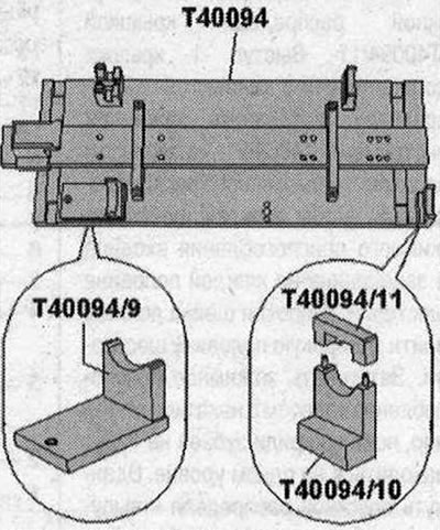
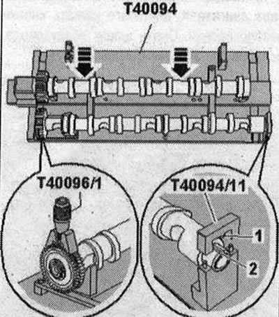
Risk of damage to the thrust bearing in the support frame. The camshafts must only be installed using the camshaft setting tool -T40094- as described below. Risk of contamination of the lubrication system and bearings. Close open engine parts. Remove any remaining sealant from the cylinder head and support frame, for example using a rotating brush with plastic bristles. Clean the seating surfaces; There should be no oil or grease on them. Lubricate the working surface of the camshafts with oil. Equip the camshaft installation tool -T40094- as follows: Screw on the supports -T40094/9- and -T40094/10- (with -T40094/11-) onto the main plate as shown in the picture. If necessary, unscrew the screwed supports at this location.
Place support -T40094/1- in position -F- and support -T40094/2- in position -A-.
Place intake camshaft on supports -T40094/1- and -T40094/2-. Rotate the intake camshaft until it can be locked in position "TDC" -arrow 1-. The concavity -arrow of the 2nd cylinder head bolt must face outwards.
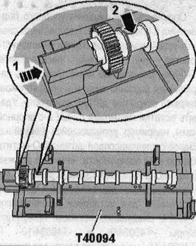
Place exhaust camshaft on supports -T40094/9- and -T40094/10-. Secure the exhaust camshaft with the cover -T40094/11-. The protrusion -1- of the cover must fit into the groove -2- in the camshaft. Position the clamping tool -T40096/1- on the exhaust camshaft gearing so that each journal of the clamping device engages on each gear half. The wide journal should fit into the wide half of the gear. Tighten the clamping device using the knurled wheel until the tooth profiles are level. Push the intake camshaft towards the exhaust camshaft until their teeth engage -arrows-.
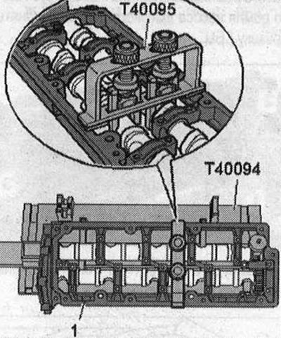
Install the frame onto the camshafts. All camshaft bearings must be on the camshafts. Install the camshaft stand -T40095- and secure the camshafts in the frame as shown in the illustration. Remove cover -T40094/11-.
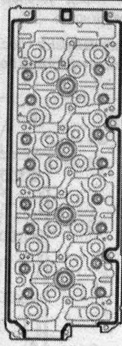
Consider the expiration date of the sealant. Cut off the tube spout at the front mark (hole diameter approx. 2 mm). Risk of contamination of camshaft bearings due to excess sealant. Sealant strips should not be thicker than the specified size. Apply a bead of sealant to the clean cylinder head mounting surfaces as shown in the illustration. Sealant strip thickness: 2...3 mm. Install and tighten the camshaft frame without delay as the sealant begins to harden immediately. After installing the crankshaft frame, allow the sealant to cure for about 30 minutes.
Remove the camshafts together with the frame, camshaft stand -T40095- and clamping tool -T40096/1- from the camshaft stand -T40094- and carefully insert into the cylinder head. Screw in the camshaft frame bolts in sequence -1...24- evenly by hand until they stop. The frame must be in contact with the cylinder head over the entire contact surface. Tighten the bolts. Remove camshaft installation tool -T40095- and clamping device -T40096/1-. Installation is in reverse order, observing the following. Install the camshaft lip seal. Press the new cover into the cylinder head using a suitable mandrel to a depth of 1...2 mm. Install the vacuum pump. Install the cylinder head cover.
Visitor comments