
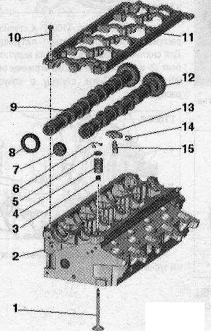
Valve mechanism 1. Valve: cannot be processed, only grinding is allowed; mark the mounting position for reinstallation; 2. Cylinder head; 3. Valve stem seal; 4. Valve spring; 5. Valve spring retainer; 6. Valve retainer; 7. Cover: replace; removal: with the camshaft frame installed, use an awl to pick up the cover on one side and remove it; installation: press in without sealant using a suitable mandrel; pressing depth 1...2 mm; 8. Shaft gasket: replace; 9. Exhaust camshaft; 10. Bolt: take into account the sequence when unscrewing; 11. Camshaft frame: with built-in camshaft bearings; 12. Intake camshaft; 13. Roller arm: mark the mounting position for reinstallation; check the roller bearings for ease of rotation; Before installation, lubricate working surfaces; 14. Hydraulic compensator locking bracket; 15. Hydraulic compensator: mark the mounting position for reinstallation; Before installation, lubricate the working surfaces
Support frame - bolt sequence and torque
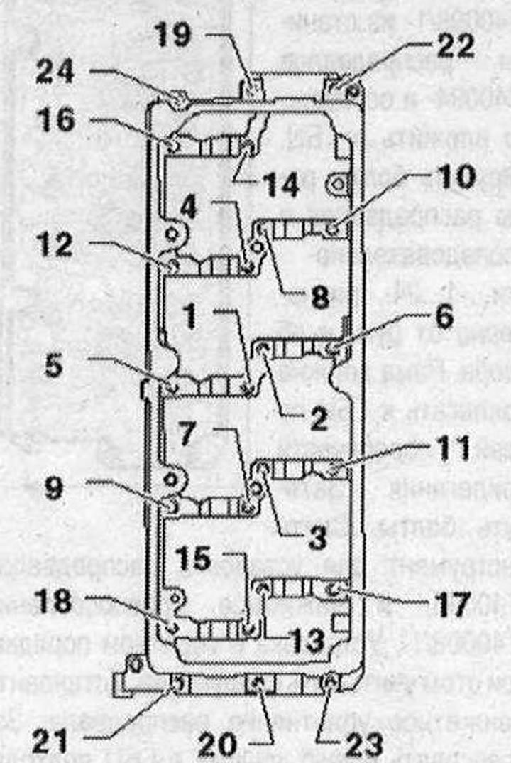
Tighten the bolts in 2 stages in the sequence shown
| Stage | Bolts | Torque |
| 1 | -1...24- | Screw in by hand until it stops. The support frame must be in contact with the cylinder head over the entire contact surface |
| 2 | -1...24- | 10Nm |
Visitor comments