
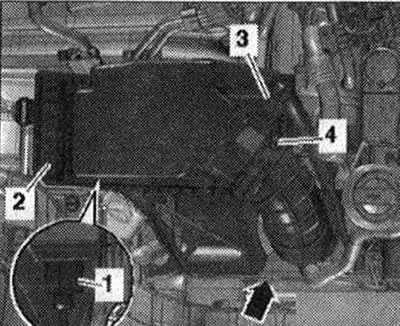
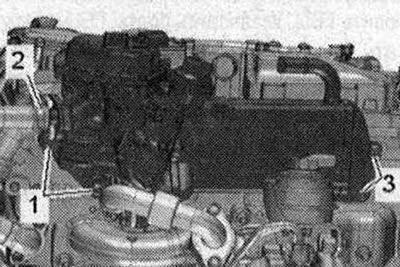
Disconnect the electrical plug connection "3" of the differential pressure sensor "G505". Unscrew the bolt "2" and release the hoses "1" from the holder. Put the differential pressure sensor "G505" back.
Release the bundle of electrical wires "arrow". Unscrew the nuts "1" and remove the holder "2".
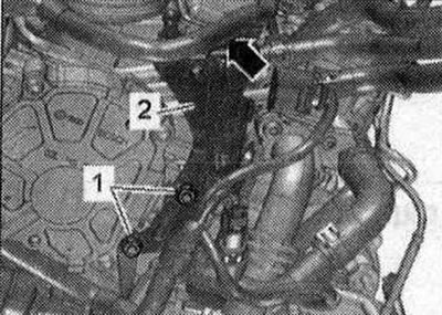
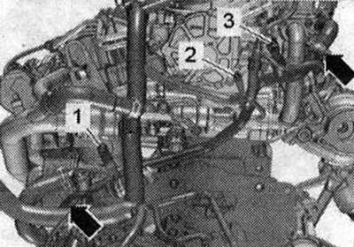
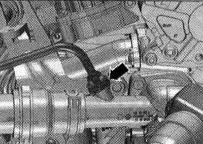
Unscrew the bolt and nut "arrows". Remove the coolant hose by loosening the hose clamp "3". Push the rear right pipe of the cooling system to the side. "Pos. 1, 2" do not take into account.
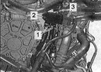
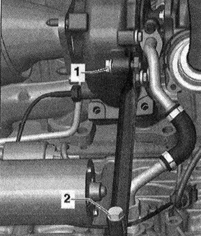
Disconnect the electrical plug connection "3". Unscrew the bolt "1". Remove the cooling system hoses from the cooling system pipe, to do this, loosen the hose clamps "arrows". Put the differential pressure sensor back. Do not take "Pos. 2" into account.
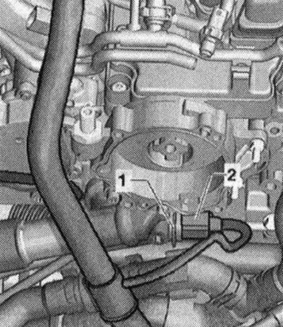
Disconnect the electrical plug connection "2" of the coolant temperature sensor "G62". "Pos. 1" is not taken into account.
Disconnect the electrical plug connection "4".
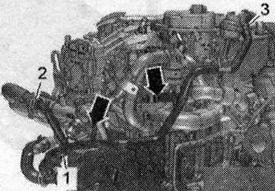
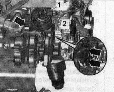
Unscrew bolt "1" of the dipstick guide tube. Disconnect electrical plug connection "3" of the throttle control unit "J338". Disregard "Pos. 2".
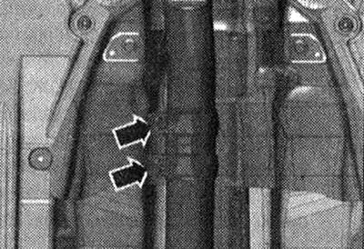
Remove the cylinder head cover. Remove the cooling system line by loosening the fastening brackets "arrows".
Loosen bolt "1" of the turbocharger. Ignore "Pos. 2".
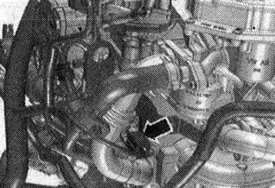
Loosen the "arrow" clamping sleeve.
Unscrew the turbocharger "arrow" nuts. "Pos. 1,2" do not take into account.
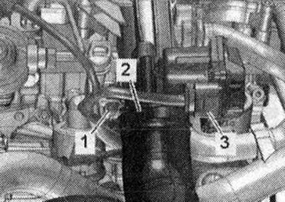
Release the wire harness on the cylinder head. Unscrew bolts "1" and "3" from the EGR radiator. Ignore "Pos. 2".
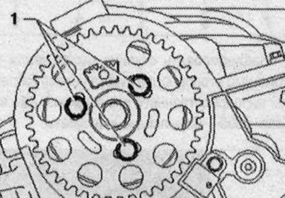
Unscrew bolts "1" and remove the camshaft timing belt gear.
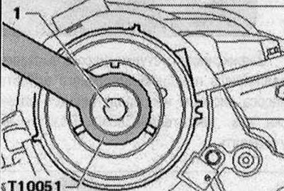
Unscrew bolt "1" of the camshaft hub, holding it with counter support "T10051". Unscrew the bolt by about 2 turns.
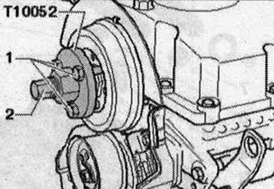
Place the puller "T10052" on the camshaft hub and screw bolts "1" into the hub. To remove the camshaft hub, screw bolt "2" and hold it by the hexagon (30) of the puller. Remove the hub from the camshaft cone.
Unscrew the bolt "arrow" of the rear toothed belt cover.
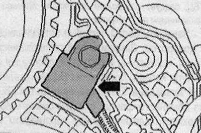
Unscrew the bolt of the Hall sensor "G40" "arrow", put the Hall sensor "G40" aside.
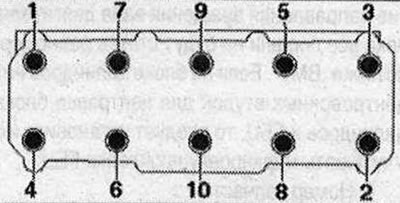
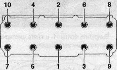
Loosen the cylinder head bolts in the sequence "1...10". A second mechanic is required to remove the cylinder head. Remove the timing belt tension roller when removing the cylinder head from the mounting pin.
Release the cylinder head backwards from the rear timing belt housing and remove the tension roller at the same time. Make sure not to damage the turbocharger oil drain line. Position the cylinder head so that the oil drain line is not kinked. If necessary, place a wooden block under the exhaust manifold. Risk of damage to the glow plug rods when installing the cylinder head. The removed cylinder head with the glow plugs installed must not be placed on the mating surface, as the glow plug rods protrude slightly beyond the mating surface. Only steel glow plugs are installed in the Audi Q5 with a 2.0 l 4V Common Rail TDI engine.
Installation
Caution! Risk of damage to the sealing surface. Carefully remove any remaining sealant from the cylinder head and cylinder block. Avoid the formation of long scratches or scoring. Risk of damage to the cylinder block. There must be no oil or coolant in the blind holes of the cylinder head fastening bolts. Risk of a leaky cylinder head gasket. Carefully remove any remaining sealant from the cylinder head and cylinder block during repairs. Avoid the formation of long scratches or scoring. Carefully remove any residue after sanding and grinding. The new cylinder head gasket must be removed from the packaging immediately before installation. To prevent damage to the silicone layer and the grooves of the cylinder head gasket, handle the gasket with particular care. Risk of damage to open valves. When installing an exchange cylinder head, remove the plastic base to protect the open valves only if it is in direct contact with the cylinder head. Risk of damage to the valves and piston crowns after working on the valve mechanism. To ensure that no valve comes into contact with the cylinder head during operation, carefully turn the crankshaft at least 2 revolutions.
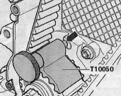
Replace bolts that were tightened with additional turning. Replace self-locking nuts, lip seals, gaskets and sealing rings. Modification of the cylinder head of TDI engines is prohibited. If a cylinder head from the exchange stock is installed, the contact surfaces between the rocker arm and the camshaft bearing housing should be lubricated. All hose connections should be secured with hose clamps of the appropriate series. After replacing the cylinder head or cylinder head gasket, it is necessary to completely replace the coolant and oil. Before installing the cylinder head, remove the crankshaft stopper "T10050" and turn the crankshaft against the direction of rotation of the engine shaft until all pistons are uniformly below "TDC". If there are no centering bushings on the cylinder block for centering the cylinder block and cylinder head, they should be installed. Take into account the marking of the cylinder head gasket.
- 1. Part number
- 2. Holes
- 3. do not take into account
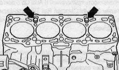
After replacing the cylinder head gasket or cylinder head, select a new cylinder head gasket in accordance with the number of holes in the old gasket. If the crank mechanism parts were replaced, then the new cylinder head gasket should be selected according to the measurements of the piston protrusion in the "TDC" position. Place the cylinder head gasket on the centering bushings "arrows" in the cylinder block. The installation position of the cylinder head gasket: marked "up" or the spare part number for the cylinder head.
Insert the cylinder head with the pin bolt of the timing belt tension roller into the recess of the protective casing of the timing belt at the rear and simultaneously put on the tension roller. Pay attention to the correct routing of the wire to the Hall sensor "G40". Install the cylinder head. Install the cylinder head bolts and screw them in by hand until they stop. Tighten the cylinder head bolts. Install the rear casing of the timing belt, the hub and the gear of the camshaft timing belt.
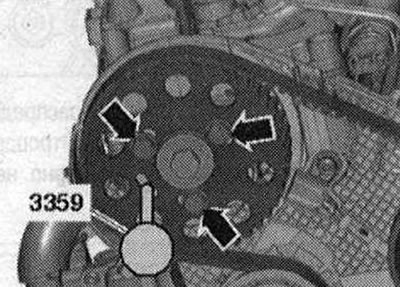
Fix the camshaft hub using the locking pin of the direct injection pump of the diesel engine "3359". Ignore the "arrows".
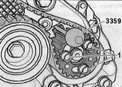
Secure the high-pressure pump hub using the locking pin of the direct injection pump of the diesel engine "3359". Ignore "Pos. 1".
Rotate the crankshaft in the direction of engine rotation until the "arrow" pin of the crankshaft stop "T10050" enters the sealing flange during rotation. Install the toothed belt (adjust the timing phases).
Installation is in the reverse order, while taking into account the following. Install the cylinder head cover. Install the poly V-belt. Install the rear coolant pipe. Install the turbocharger. Electrical connections and gasket. Install the dipstick guide tube. Connect the air duct hose using threaded clamps. Install the rear right coolant pipe. Install the differential pressure sensor "G505". Install the left upper coolant pipe. Install the air filter housing. Install the front wall of the water drain box. Change the oil. Change the coolant.