
Table of contents: Removal ↓ Installation ↓
Removal
1. Remove the engine and mount it on a suitable support or mounting stand (see the relevant chapter).
2. Remove the camshaft drive chains (see the relevant chapter).
3. Unscrew the bolts (see arrows in the illustration) and remove the camshaft position adjuster valve.
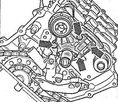
6.3. Unscrew the bolts (see arrows) and remove the camshaft position adjuster valve
4. Unscrew the bolts securing the camshaft bearing covers 1, E3, E5, A3 and A5 and remove the covers (see illustration).
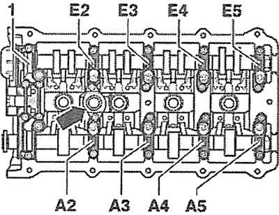
6.4. Unscrew the bolts securing the camshaft bearing covers 1, E3, E5, A3 and A5
5. Remove the oil separator (see arrow in illustration 6.4).
6. Unscrew the bolts securing the camshaft bearing caps E2, E4, A2 and A4 in a crosswise order and remove the caps (see illustration 6.4).
7. Carefully remove the intake and exhaust camshafts.
Installation
The camshafts are installed in the reverse order of removal.
8. Before installing the camshaft bearing caps, turn the crankshaft in the direction of engine rotation so that the splines on the ends of the camshafts are in a horizontal position (see arrows in the illustration). Fix the crankshaft in the TDC position of the piston of cylinder No.1.
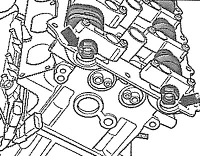
6.8. Before installing the camshaft bearing caps, turn the crankshaft in the direction of engine rotation so that the splines on the ends of the camshafts are in a horizontal position (see arrows)