
The pressure data obtained during measurement on each cylinder of a petrol engine should not differ by more than 3 bar. If the pressure in one or more cylinders differs from the pressure in other cylinders by more than 3 bar, this indicates a defect in the valves, wear of the piston rings or working surfaces of the cylinders, as well as the cylinder head gasket.
When performing a compression test, the engine oil temperature should be at least +30°C. At this oil temperature, the oil filter is warm enough to the touch. Warm up the engine if necessary.
1. Turn off the ignition.
2. Remove fuse 28 of the fuel pump (see illustration).
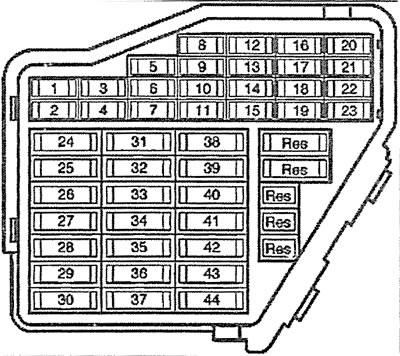
9.2. Remove fuse 28 of the fuel pump
3. Remove the engine protective covers (see arrows in the illustration).
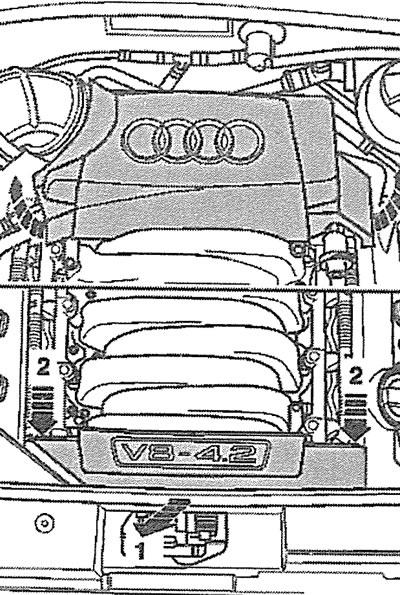
9.3 Remove the engine protective covers (see arrows)
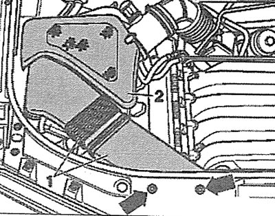
4. Unscrew the bolts (see arrows in the illustration) expansion tank 2 mounts for the coolant and move the tank away from the work area without disconnecting hoses 1 and 3 from it. The coolant level sensor wire must be disconnected.
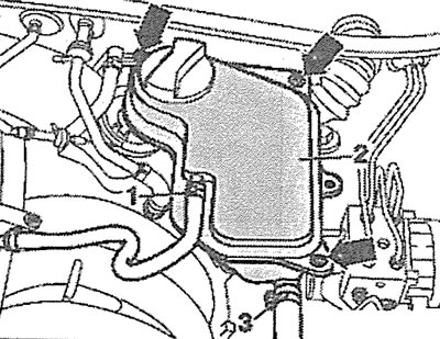
9.4. Unscrew the bolts (see arrows) expansion tank 2 mounts for the coolant and move the tank away from the work area without disconnecting hoses 1 and 3 from it
5. Remove the cap from the power steering fluid reservoir (see arrow in illustration).
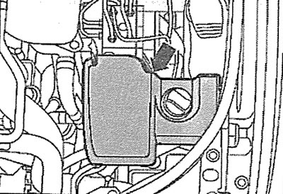
9.5. Remove the cap from the power steering fluid reservoir (see arrow)
6. Unscrew the bolt (see arrow in illustration) fastenings of the guide tube of the oil dipstick.
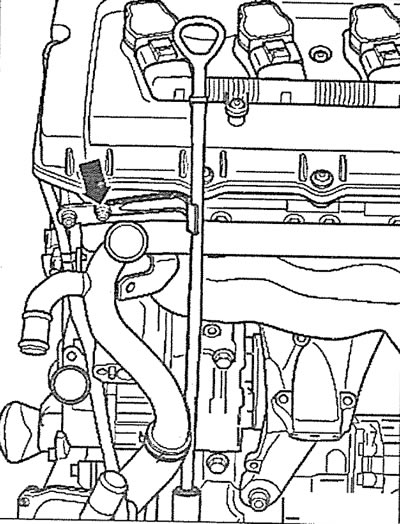
9.6. Unscrew the bolt (see arrow) oil dipstick guide tube mounts
7. Remove the air filter cover 2 and remove the clips (see arrows in the illustration) and remove air duct 1.
9.7. Remove the air filter cover 2 and remove the fasteners (see arrows) and remove the air duct 1
8. Release plug 3 of the solenoid valve of the adsorber from the holder 2 (see illustration), then remove the valve.
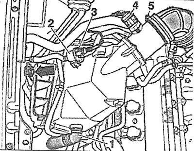
9.8. Release plug 3 of the solenoid valve of the adsorber from the holder 2
9. Disconnect plug 4 of the mass air flow sensor (see illustration 9.8).
10. Disconnect hose 1 of the fresh air supply pump to the outlet valves (see illustration 9.8).
11. Remove clamp 5 and disconnect the supply air duct from the air filter housing.
12. Unscrew the bolt (see arrow in illustration 9.8) fasteners and remove the air filter housing together with the mass air flow sensor.
13. Disconnect plugs 1-4 from the ignition coils, unscrew bolts 5 and 6 and move the coil wiring harness away from the work area (see illustrations 9.13 and 9.13a). Then carefully remove the ignition coils (see arrows in illustrations 9.13 and 9.13a).
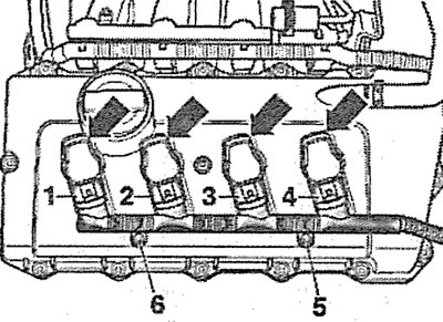
9.13. Disconnect plugs 1-4 from the ignition coils, unscrew bolts 5 and 6 and move the coil wiring harness away from the work area. Then carefully remove the ignition coils (see arrows). Left cylinder head |
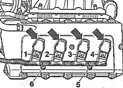
9.13a. Disconnect plugs 1-4 from the ignition coils, unscrew bolts 5 and 6 and move the coil wiring harness away from the work area. Then carefully remove the ignition coils (see arrows). Right cylinder head |
14. Screw the compression tester into the spark plug socket, following the instructions for use.
15. Ask an assistant to hold the accelerator pedal depressed until the check is complete.
16. Let the engine turn over approximately 8 revolutions until the pressure registered by the compression gauge stops increasing. Read the compression gauge readings.
17. Install the removed components in the reverse order of removal.
Attention! The engine control unit registers disconnection of the plugs as a malfunction. In this regard, it is recommended to contact a workshop at the earliest opportunity to delete the entry.
Compression Values Table
| nominal value | maximum permissible value | |
| Compression, bar | 10-14 | 9 |