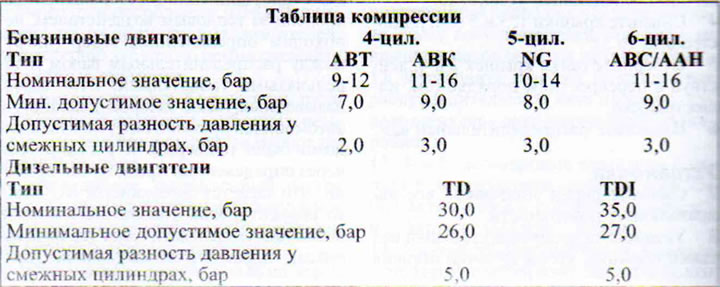
Table of contents: Petrol engines ↓ Diesel engines ↓
Compression testing allows you to draw conclusions about the overall condition of the engine, as well as the condition and operation of its components. This primarily concerns valves and piston rings. Cold engine starting, effective power, oil and fuel consumption, and exhaust gas composition depend on their tightness. A compression tester with a corresponding adapter is needed for testing.
The test is performed on an engine warmed up to operating temperature.
Petrol engines
1. Four-cylinder engine: Disconnect the ignition coil output stage connector.
2. Disconnect the multi-pin connector from the fuel injection system unit (66 kW engine) or the power plug for all four valve injectors (85 kW engine).
3. Five-cylinder engine. Disconnect the ignition coil output stage connector.
4. Remove fuse #17 from the fuse box.
5. Six-cylinder engine. Disconnect both ignition coil output stage connectors.
6. Disconnect the plugs of all six valve injectors.
7. Disconnect the high-tension wire holders of the spark plugs of the third and fourth cylinders.
8. All engines. Remove spark plugs.
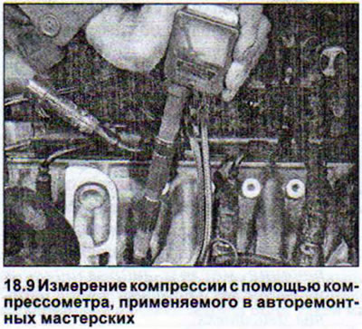
9. Insert the rubber cone of the compression tester into the spark plug hole of cylinder #1 or screw the tip of the adapter into the spark plug hole. The sequence of compression testing is not important. It is recommended to only write down the number of the cylinder tested (see illustration).
10. Apply the handbrake.
11. Set the gearbox to neutral. For vehicles with automatic transmission, set the gearbox control lever to position "R".
12. Ask an assistant to turn the engine with the starter. The accelerator pedal should be pressed all the way down to better fill the cylinders.
13. Record the reading as soon as the pressure in the cylinder stops increasing.
14. Proceed to measure compression on the next cylinder.
Diesel engines
15. Disconnect the power supply wire of the fuel cut-off valve on the high-pressure fuel pump.
16. TD engines: Disconnect the fuel lines from the injectors and place them on a clean rag.
17. Unscrew all valve injectors.
18. Remove the heat shields from the injector holes.
19. TD1 engines. Remove the glow plug caps and unscrew the glow plugs themselves.
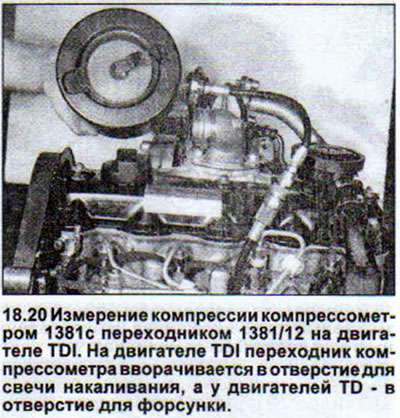
20. All engines. Screw the adapter tip into the injector or glow plug hole of cylinder #1. When checking compression on a TD engine, place the old heat shield under the tip (see illustration).
21. Set the gearbox to neutral position.
22. Start the starter and wait until the pressure indicated by the compression gauge stops increasing.
23. Write down the obtained value.
24. Proceed to measure compression on the next cylinder.
After completing the check, tighten the glow plugs on the TD1 engine to 15 Nm, and on TD engines, install new heat-shielding gaskets under the valve injectors. Tighten the valve injectors to 70 Nm, and the fuel line nuts on the injectors to 25 Nm.
Uniformly low compression, not exceeding the permissible minimum values, is not a cause for concern. Lower values may be the result of the influence of tolerances inherent in each type of compression meter. A cause for concern is an increased pressure difference in adjacent cylinders. For gasoline engines, it should not exceed 2-3 bar. The reasons for the appearance of higher values may be:
- wear of pistons and piston tracks,
- piston ring seizure due to deposits,
- cylinder deformation due to piston seizure,
- accumulated deposits on valve stems,
- burnt and leaky valves. In most cases, leaky valves are the cause of low compression and a drop in effective engine power. This defect can only be eliminated by overhauling the cylinder head.
To determine the cause of compression loss in gasoline engines, use the following method. Use an oil can to drip a few drops of engine oil into the spark plug hole and measure the compression again. If the readings are still bad, the reason is leaky valves. If the pressure has increased, the reason for its decrease is the piston rings or even the cylinders themselves. The dripped oil created a hermetic film between the pistons and the cylinder walls for some time, thus preventing gases from leaking out.
More accurate data on the causes of the compression pressure drop can be obtained by performing a compression test with compressed air. This test is performed by many workshops. During this test, compressed air is supplied to the combustion chamber through the spark plug hole. The pressure drop in the combustion chamber is recorded by a compression meter, and the air leak can be determined by ear.
Compressed air escaping from the exhaust pipe, accompanied by a hissing sound, indicates that the exhaust valve is leaking. If compressed air is escaping from the air filter, this indicates that the intake valve is leaking. If the cylinder head gasket is defective or the head is cracked, compressed air is released through the opening of the nearby spark plug or through the open expansion tank with coolant. If the cylinder walls, piston guides or piston rings are worn, compressed air enters the crankcase and exits through the open oil filler pipe or through the guide tube of the dipstick.