
Table of contents: Removal ↓ Installation ↓
Removal
Attention! The cylinder head is removed with the engine removed.
1. Remove the engine and mount it on a suitable support or mounting stand (see the relevant chapter).
2. Remove the camshaft drive chains (see the relevant chapter).
3. Remove the accessory drive chain (see the relevant chapter).
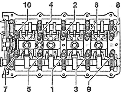
4. Unscrew the cylinder head mounting bolts in the sequence shown in the illustration and carefully remove the head from the cylinder block.
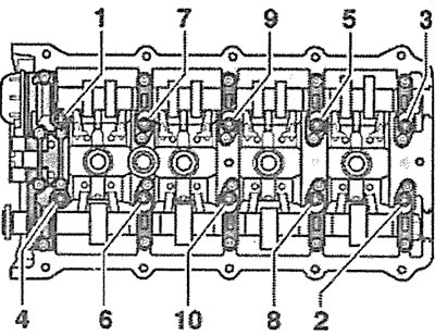
7.4. Unscrew the cylinder head mounting bolts in the specified sequence
Installation
The cylinder head is installed in the reverse order of removal.
5. Check the condition of the cylinder head and make sure there are no cracks or dents.
6. Clean the threads of the cylinder head bolt holes. There should be no oil or other contaminants in these holes. If necessary, blow out the holes with compressed air or clean them with a screwdriver wrapped in a rag that absorbs liquid. Oil can be collected from the holes with a grease gun. If this is not done, then when screwing in the bolts, excess pressure will be created in the holes, which can lead to a rupture of the cylinder block or incorrect tightening torque of the bolts.
7. Remove the remains of the old seal from the surface of the cylinder block and head using a plastic scraper. Do not allow dirt and seal remains to get into the cylinder bores. Cover the cylinder bores with a rag.
Attention! Cleaning the sealing surfaces with a metal brush or other metal tool is not permitted.
8. Check the cylinder head for warpage, deformation or distortion using a feeler gauge and a steel ruler (see illustration). The maximum permissible head warpage should not exceed 0.1 mm. Cylinder head modification is allowed up to the minimum dimension "a", which is 139.25 mm (see illustration 7.8a).
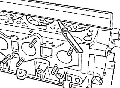
7.8. Check the cylinder head for warpage, deformation or distortion using a feeler gauge and a steel ruler |
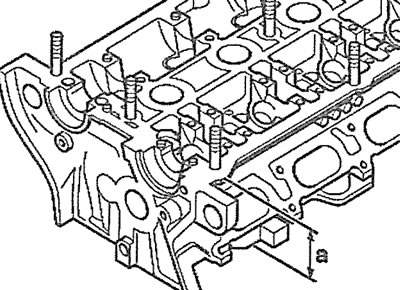
7.8a. Modification of the cylinder head is permitted up to the minimum dimension "a", which is 139.25 mm |
9. Inspect the removed cylinder head gasket and, if the pistons, connecting rods or crankshaft have not been replaced, install a new gasket of the same thickness as the old one. The "Oben/Top" marking on the gasket should face upwards, towards the cylinder head, when installing it.
10. Make sure the locating pins are positioned correctly (see arrows in the illustration).
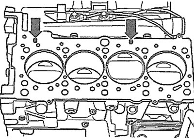
7.10. Make sure the dowel pins are positioned correctly (see arrows)
11. Tighten the cylinder head bolts in several passes in the sequence shown in the illustration:
- 1st pass - tighten the bolts to 30 Nm;
- 2nd pass - tighten the bolts to 60 Nm;
- 3rd pass - tighten the bolts by 90°;
- 4th pass - tighten the bolts 90° further.
7.11 Tighten the cylinder head bolts in several passes in the sequence shown
[Content source: the specified website: AUDIMANUAL]