
Table of contents: Removal ↓ Installation ↓
Removal
Caution! When removing the V-belt of the alternator drive, it will be necessary to install the upper front crossmember (see illustration 5.0a) into the service position, for which it is necessary to perform the following steps.
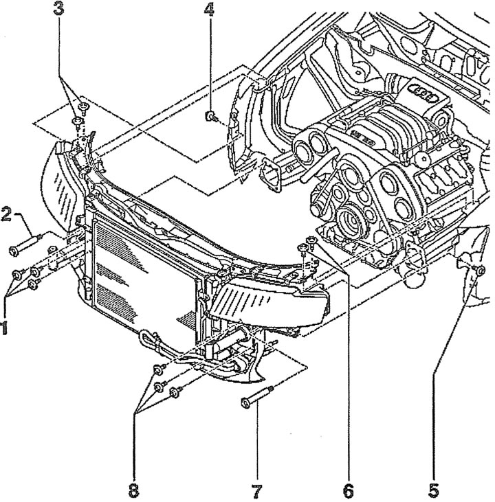
5.0a. Front crossmember details:
1 - bolts. Tightening torque - 50 Nm
2, 7 - device for installing the front cross member in the service position. Catalog number of the device - 3369
3 - bolts. Tightening torque -10 Nm
4 - bolts. Tightening torque - 10 Nm
5 - bolts. Tightening torque - 10 Nm
6 - bolts. Tightening torque -10 Nm
8-bolts. Tightening torque - 50 Nm
9 - front cross member assembly
Attention! If the specified special device is not available, then you can use two M8x90 bolts, on which spacer washers with an outer diameter of 24 mm and a thickness of about 2 mm are installed. In addition, you will need two bushings 80 mm long and 17 mm in diameter.
1. Cars with parking heater. Unscrew the bolts (see arrows in the illustration) fastening the heater pipe to the soundproofing shield.
5.1. Unscrew the bolts (see arrows) fastening the heater pipe to the soundproofing shield. Cars with a parking heater
2. Remove the front bumper (see the relevant chapter).
3. Unscrew bolts/remove fasteners 1-2 and remove the front part of the engine mudguard (see illustration).
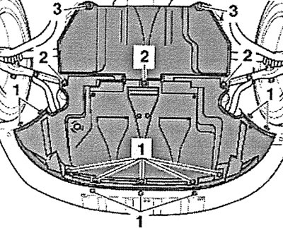
5.3. Unscrew bolts/remove fasteners 1-2 and remove the front part of the engine mudguard
4. Remove the power steering fluid reservoir cap (see arrow in illustration).
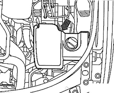
5.4. Remove the power steering fluid reservoir cap (see arrow)
5. Release plugs 1 and 2 from the holders and move the wiring harness away from the work area (see illustration).
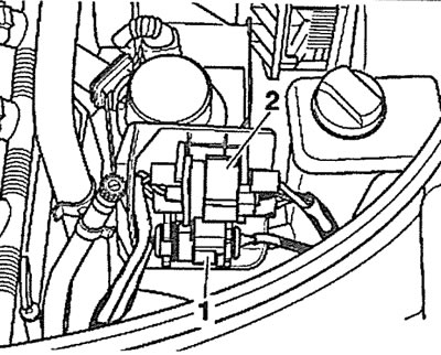
5.5. Release plugs 1 and 2 from the holders and move the wiring harness away from the work area
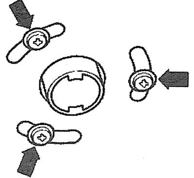
6. Press the latches and remove the air filter cover 2 (see illustration).
5.6. Press the latches and remove the air filter cover 2
7. Unscrew the bolts (see arrows in illustration 5.5) fastening the air intake 1 to the upper front cross member and remove the air intake.
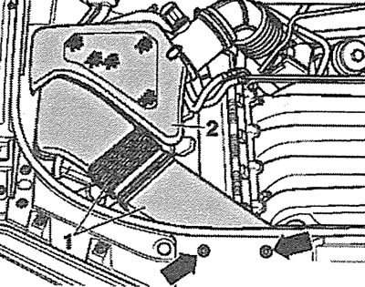
8. Remove the left fairing (see arrow in illustration 5.8) and the right fairing (see arrow in illustration 5.8a) additional radiator.
5.8. Remove the left fairing (see arrow) additional radiator
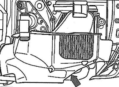
5.8a. Remove the right fairing (see arrow) additional radiator
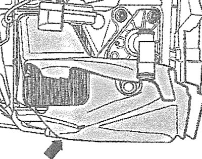
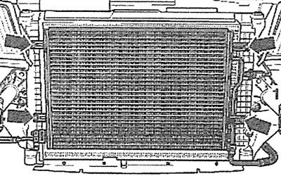
9. Unscrew the bolts (see arrows in the illustration), press the fasteners and remove the left and right radiator fairings.
5.9. Unscrew the bolts (see arrows), press the clamps and remove the left and right radiator fairings
10. Disconnect the outside air temperature sensor 1 and release the wire from the holder (see illustration).
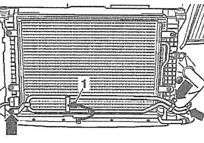
5.10. Disconnect the outside air temperature sensor 1 and release the wire from the holder
11. Unscrew the bolts (see arrows in illustration 5.10) power steering line holders and move the line away from the work area without opening the system. Carefully tie up the line to avoid damaging it.
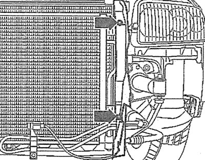
12. Vehicles with air conditioning. Disconnect plug 1 of the refrigerant pressure sensor (see illustration).
5.12. Disconnect plug 1 of the refrigerant pressure sensor. Vehicles with air conditioning
13. Cars with air conditioning. Unscrew the bolts (see arrows in illustration 5.12) air conditioner radiator mounts and remove the radiator. Carefully tie the radiator to the body with wire, without disconnecting the hoses and refrigerant circulation pipes from it. Do not allow the hoses to bend or twist.
Attention! All work related to the air conditioner should be entrusted to a specialized workshop. Do not open the refrigerant circulation system yourself - risk of frostbite!
14. Unscrew the bolts (see arrows in the illustration) on the right and left sides of the upper front cross member.
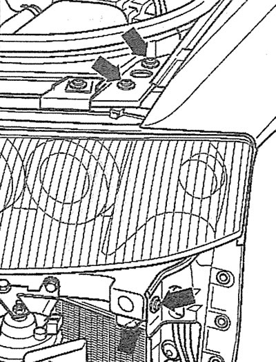
5.14. Unscrew the bolts (see arrows) on the right and left sides of the upper front cross member
15. Screw the 3369 tools into the holes on the left and right, then unscrew the shock absorber mounting bolts (see arrows in the illustration) and carefully push the crossbar forward.
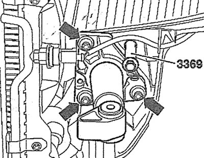
5.15. Screw the 3369 fixtures into the holes on the left and right, then unscrew the shock absorber mounting bolts (see arrows)
16. Mark the direction of rotation of the alternator drive V-belt with chalk, marker or paint if the belt is to be reinstalled. Failure to maintain the previous belt rotation during further operation may result in damage or breakage.
17. Loosen the tightening and then unscrew the bolt (see arrow in illustration) fastenings of the generator drive belt tensioner and carefully remove the belt.
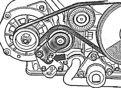
5.17. Loosen the tightening and then unscrew the bolt (see arrow) fastenings of the alternator drive belt tensioner and carefully remove the belt
Installation
18. Place the V-belt first on the generator pulley, then on the freewheel clutch, vibration damper and tension roller (see illustration).
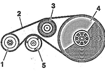
5.18. Sequence of laying the V-belt: 1 - generator; 2 - V-belt; 3 - freewheel clutch; 4 - vibration damper; 5 - tension roller
19. Turn the tension roller eccentric with a VAG 1332 torque wrench to 70 Nm and tighten the bolt at the same time (see arrow in illustration) tensioner fastenings with a force of 22 Nm.
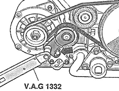
5.19. Turn the tension roller eccentric with a VAG 1332 torque wrench to 70 Nm and tighten the bolt at the same time (see arrow) tensioner fastenings with a force of 22 Nm
Next, the installation of the dismantled components is carried out in the reverse order of removal.
[This article was copied from the website AUDIMANUAL.RU]