
Table of contents: Removal ↓ Installation ↓
Removal
1. Remove the engine and mount it on a suitable support or mounting stand (see the relevant chapter).
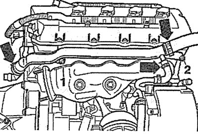
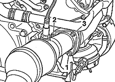
2. Disconnect plug 1 from the throttle valve, and also remove clamp 2 and disconnect the crankcase ventilation hose (see illustration).
3.2. Disconnect plug 1 from the throttle valve, and also remove clamp 2 and disconnect the crankcase ventilation hose
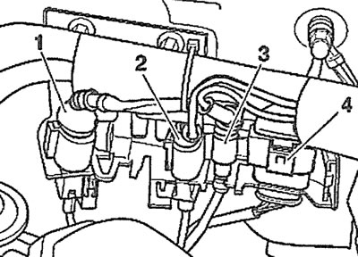
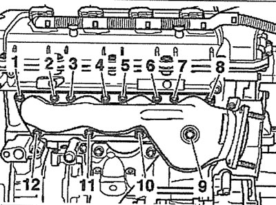
3. Disconnect plugs 1, 2, 5 and 6 from the intake manifold bracket, then disconnect plugs 3 and 4 (see illustration).
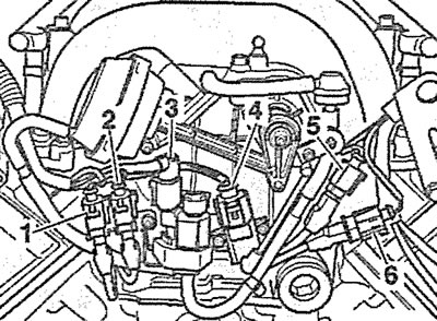
3.3. Disconnect plugs 1, 2, 5 and 6 from the intake manifold bracket, then disconnect plugs 3 and 4
4. Disconnect the low pressure hose (see arrow in illustration).
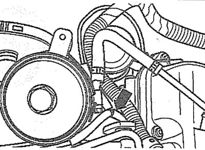
3.4. Disconnect the low pressure hose (see arrow)
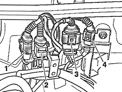
5. Disconnect the fuel injector plugs on rails 6 and 7, the wires of which are combined into harnesses 1 and 5 (see illustration).
3.5. Disconnect the fuel injector plugs on rails 6 and 7, the wires of which are combined into harnesses 1 and 5
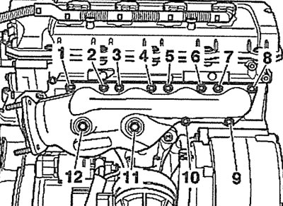
6. Disconnect low pressure hose 4 from the fuel pressure regulator (see illustration 3.5).
7. Unscrew bolts 2 and 3 and remove ramps 6 and 7 together with fuel injectors (see illustration 3.5).
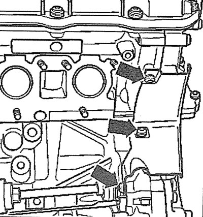
8. Unscrew the mounting bolts (see arrows in the illustration) and remove the rear left engine lifting eye.
3.8. Unscrew the mounting bolts (see arrows) and remove the rear left engine lifting eye
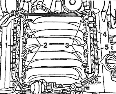
9. Unscrew the mounting bolts (see arrows in the illustration) and remove the intake manifold.
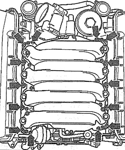
3.9. Unscrew the mounting bolts (see arrows) and remove the intake manifold
Caution! The cylinder head intake ports must be covered with a clean cloth.
10. Unscrew the lid (see arrow in illustration) oil filter and remove the replaceable filter element from the filter housing.
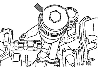
3.10. Unscrew the lid (see arrow) oil filter
11. Drain the engine oil from the oil filter using a special device for pumping out, the catalog number of which is VAG1358 or VAG1782. Wrap the oil filter housing with a rag to collect the leaking engine oil.
12. Unscrew the bolts (see arrows in the illustration) fasteners and remove the oil filter.
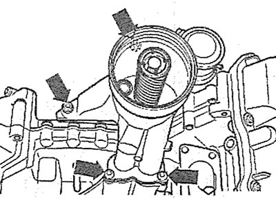
3.12. Unscrew the bolts (see arrows) fasteners and remove the oil filter
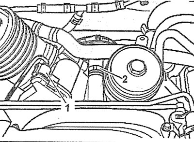
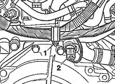
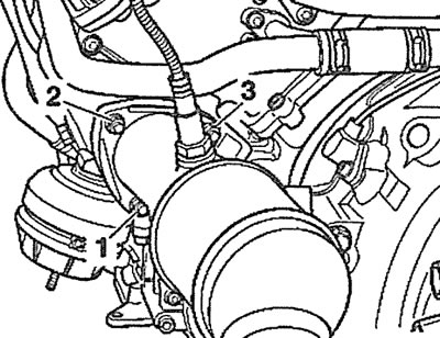
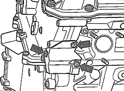
13. Disconnect plug 1 from the engine support, unscrew nut 2 and remove the support (see illustration).
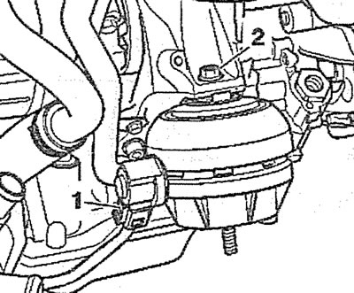
3.13. Disconnect plug 1 from the engine support, unscrew nut 2 and remove the support
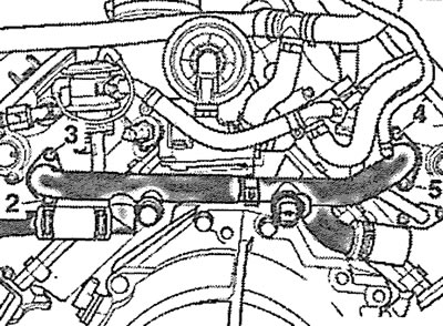
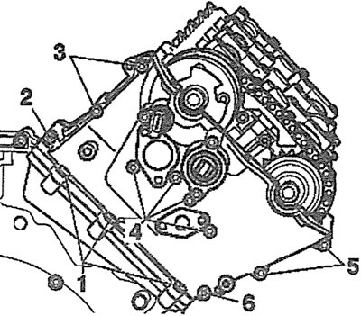
14. Unscrew bolts 1 and 2 of the power steering return line holders, remove the clamp (see arrow in illustration) and remove the pipeline.
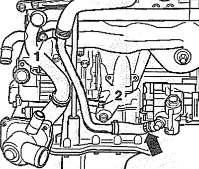
3.14. Unscrew bolts 1 and 2 of the power steering return line holders, remove the clamp (see arrow) and remove the pipeline
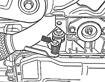
15. Unscrew the bolt (see arrow in illustration) the guide tube holder of the measuring probe and remove the tube by pushing it upward.
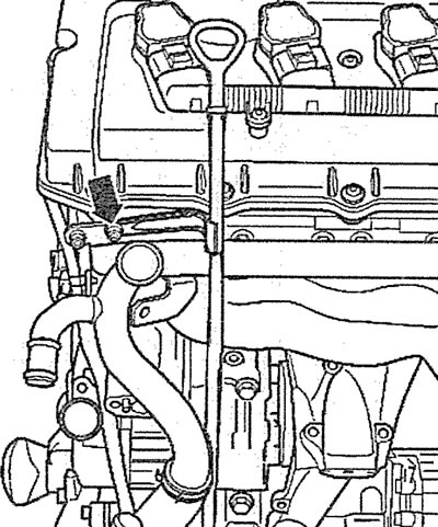
3.15. Unscrew the bolt (see arrow) the measuring probe guide tube holder and remove the tube by pushing it upwards
16. Unscrew bolts 1 and 2, remove the mounting clamps (see arrows in illustrations 3.16 and 3.16a) and disconnect the coolant circulation lines.
3.16. Unscrew bolts 1 and 2, remove the mounting clamps (see arrows) and disconnect the coolant circulation line. Left cylinder head
3.16a. Unscrew bolts 1 and 2, remove the mounting clamps (see arrows) and disconnect the coolant circulation line. Right cylinder head
17. Disconnect plug 2 of the coolant temperature sensor, then unscrew nut 1 and disconnect the wiring harness (see illustration).
3.17. Disconnect plug 2 of the coolant temperature sensor, then unscrew nut 1 and disconnect the wiring harness
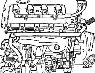
18. Unscrew bolts 2-5 of the coolant pipe holders and remove the pipe (see illustration).
3.18. Unscrew bolts 2-5 of the coolant pipe holders and remove the pipe
19. Unscrew bolts 1-4 securing the fresh air intake valves to the exhaust valves (see illustration).
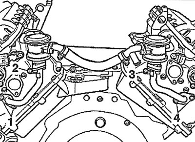
3.19. Unscrew bolts 1-4 securing the fresh air intake valves to the exhaust valves
20. Disconnect the plugs 1-4 of the lambda probes (oxygen sensors) and release the wires from the holders (see illustrations 3.20 and 3.20a).
3.20. Disconnect plugs 1-4 and release the wires from the holders. Left cylinder head |
3.20a. Disconnect plugs 1-4 of lambda probes (oxygen sensors) and release the wires from the holders. Right cylinder head |
21. Right cylinder head. Unscrew the bolt (see arrow in illustration) fastenings of the inlet pipe lining.
3.21. Unscrew the bolt (see arrow) fastenings of the inlet pipe lining. Right cylinder head
22. Unscrew nuts 1-3 securing the inlet pipe to the exhaust manifold and disconnect the pipe (see illustrations 3.22 and 3.22a).
3.22. Unscrew nuts 1-3 securing the inlet pipe to the exhaust manifold and disconnect the pipe. Left cylinder head |
3.22a. Unscrew nuts 1-3 securing the intake pipe to the exhaust manifold and disconnect the pipe. Right cylinder head |
23. Unscrew nuts 1-12 and remove the exhaust manifold (see illustrations 3.23 and 3.23a).
3.23. Unscrew nuts 1-12 and remove the exhaust manifold. Left cylinder head |
3.23a. Unscrew nuts 1-12 and remove the exhaust manifold. Right cylinder head |
24. Unscrew the bolts (see arrows in illustrations 3.24 and 3.24a) and remove the heat shields.
3.24. Unscrew the bolts (see arrows) and remove the heat shield. Left cylinder head |
3.24a. Unscrew the bolts (see arrows) and remove the heat shield. Right cylinder head |
25. Disconnect plugs 1-4 from the ignition coils, unscrew bolts 5 and 6 and move the coil wiring harness away from the work area (see illustrations 3.25 and 3.25a). Then carefully remove the ignition coils (see arrows in illustrations 3.25 and 3.25a).
3.25. Disconnect plugs 1-4 from the ignition coils, unscrew bolts 5 and 6 and move the coil wiring harness away from the work area |
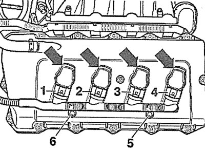
3.25a. Disconnect plugs 1-4 from the ignition coils, unscrew bolts 5 and 6 and move the coil wiring harness away from the work area. Then carefully remove the ignition coils (see arrows). Right cylinder head |
26. Remove the clamp (see arrow in illustrations 3.26 and 3.26a) fasteners and disconnect the crankcase ventilation hose.
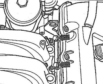
3.26. Remove the clamp (see arrow) fasteners and disconnect the crankcase ventilation hose. Left cylinder head |
3.26a. Remove the clamp (see arrow) fasteners and disconnect the crankcase ventilation hose. Right cylinder head |
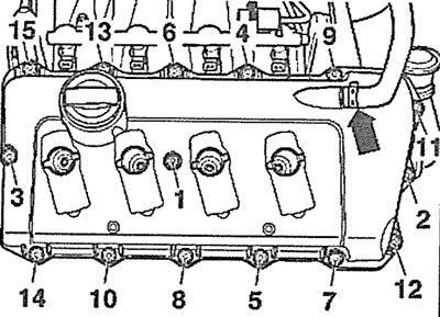
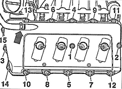
27. Unscrew the cylinder head cover mounting bolts in descending order of their numbering - 15-1 - and remove the cylinder head cover (see illustrations 3.26 and 3.26a).
28. Disconnect the plug (see arrow in illustrations 3.28 and 3.28a) from the camshaft position sensor(hall sensor).
3.28. Disconnect the plug (see arrow) from the camshaft position sensor (hall sensor). Left cylinder head |
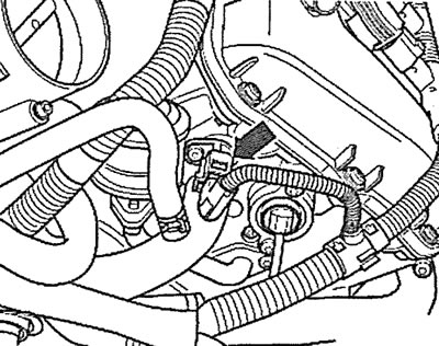
3.28a. Disconnect the plug (see arrow) camshaft position sensor (hall sensor). Right cylinder head |
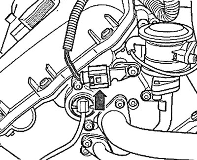
29. Unscrew the nut (see arrow in illustration) and disconnect the ground (-) wire from the right cylinder head, move the wiring harness away from the work area.
3.29. Unscrew the nut (see arrow) and disconnect the ground (-) wire from the right cylinder head
30. Unscrew bolts 1-6 and remove the left part of the timing gear protective cover (see illustration).
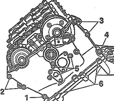
3.30. Unscrew bolts 1-6 and remove the left part of the timing gear protective cover
31. Unscrew bolts 1-6 and remove the right part of the timing gear protective cover (see illustration).
3.31. Unscrew bolts 1-6 and remove the right part of the timing gear protective cover
32. Turn the crankshaft in the direction of engine rotation using the special lining T40049, which is attached to the flange on the crankshaft with two bolts (see illustration 3.32). The crankshaft must be turned so that the splines on the rear ends of the camshafts are horizontal (see arrows in illustration 3.32a).
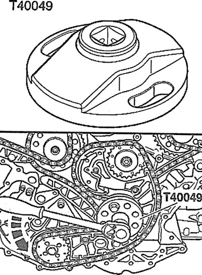
3.32 Turn the crankshaft in the direction of engine rotation |
3.32a. Turn the crankshaft in the direction of engine rotation so that the splines on the rear ends of the camshafts are horizontal (see arrows) |
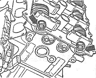
33. Lock the camshafts with a special stop bar, catalog number T40046 (see illustration). If the bar cannot be installed without any problems, turn the crankshaft one more revolution (360°).
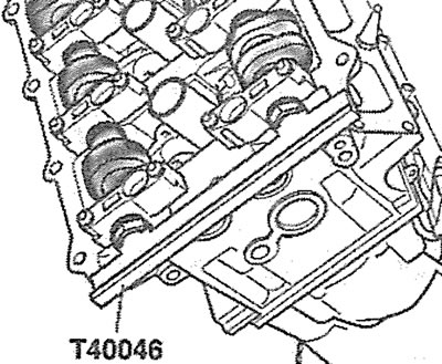
3.33. Lock the camshafts with a special stop bar, catalog number T40046
Caution! The stop bar must not be used as a stop when tightening the sprocket shaft mounting bolts.
Attention! Since after locking the camshafts, it is necessary to lock the crankshaft, which may have to be turned to install the thrust pin, the camshafts can be fixed later.
34. Unscrew the plug from the bottom of the cylinder block and screw in the thrust pin 3242 in its place to lock the crankshaft (see illustration). If necessary, turn the crankshaft slightly to the right or left so that the stop enters the corresponding hole on the crankshaft cheek. The tightening torque of the stop pin is 20 Nm.
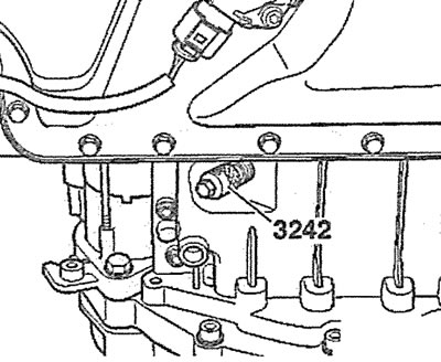
3.34. Unscrew the plug from the bottom of the cylinder block and screw in the thrust pin 3242 instead to lock the crankshaft
Caution! Stop 3242 must not be used as a stop when tightening bolts.
35. Lock the camshafts with the T40046 stop bar (see illustration 3.33), if they have not been blocked previously.
36. Press the intake camshaft timing chain of the left/right cylinder head (see arrow in illustrations 3.36 and 3.36a), to press the chain tensioner plunger, and in this position, fix the tensioner with a drill 1 with a diameter of 3.3 mm, inserting it into the hole in the tensioner body.
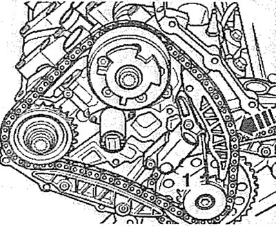
3.36. Press on the camshaft drive chain of the left cylinder head intake valves (see arrow), to press the plunger of the chain tensioner, and in this position fix the tensioner with a drill 1 with a diameter of 3.3 mm, inserting it into the hole on the tensioner body |
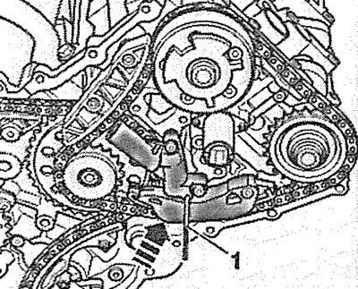
3.36a. Press on the intake camshaft drive chain of the right cylinder head (see arrow), to press the plunger of the chain tensioner, and in this position fix the tensioner with a drill 1 with a diameter of 3.3 mm, inserting it into the hole on the tensioner body |
37. Unscrew bolts 1 and 2 securing the sprocket to the intake camshaft and the camshaft position adjuster and remove the sprocket and adjuster (see illustrations 3.37 and 3.37a).
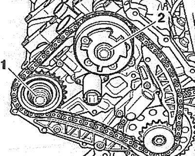
3.37. Unscrew bolts 1 and 2 securing the sprocket to the intake camshaft and the camshaft position adjuster and remove the sprocket, adjuster and drive chain. Left cylinder head |
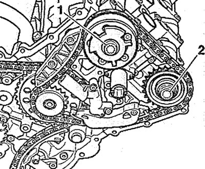
3.37a. Unscrew bolts 1 and 2 securing the sprocket to the intake camshaft and the camshaft position adjuster and remove the sprocket, adjuster and drive chain. Right cylinder head |
Installation
Installation of the camshaft drive chains is carried out in the reverse order of removal.
Caution: The intake camshaft position sensor gear, which is located on the camshaft position adjuster, must be in the correct position after installing the chain.
38. Place the intake camshaft drive chain on the sprocket and adjuster, install them together with the chain in their places and screw in the sprocket and adjuster mounting bolts by hand.
39. Pre-tighten the bolt securing the sprocket to the intake camshaft to 40 Nm.
40. Install the special tool T40047 on the regulator and the camshaft position sensor gear, and its other end on the head of bolt 1 securing the sprocket to the intake camshaft (see illustrations 3.40 and 3.40a).
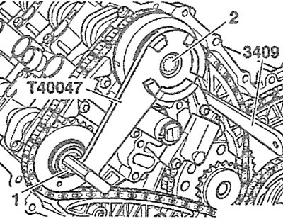
3.40. Install special tool T40047 on the regulator and the camshaft position sensor gear, and its other end on the head of bolt 1 for fastening the sprocket to the intake camshaft. Left cylinder head: 3409 - wedge that presses the chain tensioner plunger |
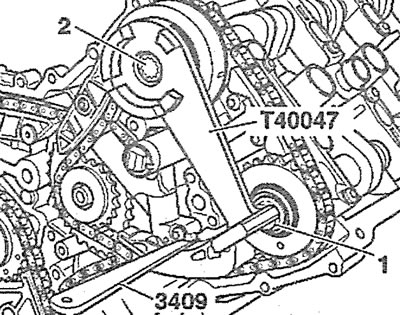
3.40a. Install special tool T40047 on the regulator and the camshaft position sensor gear, and its other end on the head of bolt 1 for fastening the sprocket to the intake camshaft. Right cylinder head: 3409 - wedge that presses the chain tensioner plunger |
41. Pre-tighten bolt 2 of the camshaft position adjuster with a force of 40 Nm (see illustrations 3.40 and 3.40a).
42. Remove the T40047 tool and perform the final tightening of the sprocket mounting bolt to the intake camshaft in several passes: 1st pass - tighten the bolt to 100 Nm; 2nd pass - turn the bolt 90° further.
43. Reinstall the T40047 tool and tighten the camshaft position adjuster mounting bolt in several passes: 1st pass - tighten the bolt with a force of 100 Nm; 2nd pass - turn the bolt 90° further.
The original article is located on the online resource AUDIMANUAL.ru