
Table of contents: Removal ↓ Installation ↓
Removal
1. Drain the engine oil.
2. Remove the engine and mount it on a suitable support or mounting stand (see the relevant chapter).
3. Lock the drive disk by installing a thrust shoe 10-201 on its toothed ring (see illustration), having previously marked its installation position.
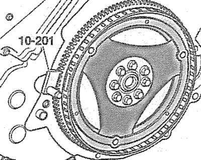
4.3. Lock the drive disk by installing a thrust shoe 10-201 on its toothed ring
4. Unscrew the mounting bolts and remove the drive disk from the crankshaft.
5. Remove the timing chain protective covers.
6. Press the chain at the point marked by the arrow in the illustration and secure the oil and water pump drive chain tensioner in this position using a 3.3 mm diameter drill bit 1 by inserting it into the hole in the tensioner housing.
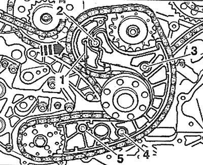
4.6. Press the chain at the point marked with the arrow and in this position fix the chain tensioner with a drill 1 with a diameter of 3.3 mm, inserting it into the hole in the tensioner body
7. Unscrew bolts 2-5 securing the oil and water pump drive chain tensioner and remove the tensioner (see illustration 4.6).
8. Carefully remove the drive chain of the oil and water pumps.
Installation
The installation of the auxiliary drive chain is carried out in the reverse order of removal.
9. The tightening torque of the chain tensioner mounting bolts is 10 Nm.
10. Tightening of the drive disk mounting bolts is carried out in several passes: 1st pass - 30 Nm; 2nd pass - tighten the bolts by 90°.